Introduction
Internal Prerequisite.
-
-
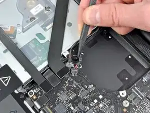
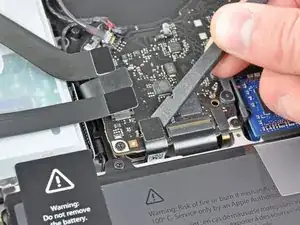
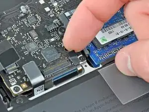
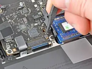
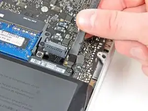
Use the tip of a spudger to pull the right speaker/subwoofer cable out from under the retaining finger molded into the upper case.
-
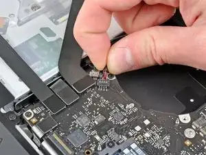
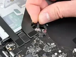
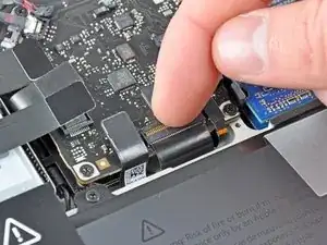
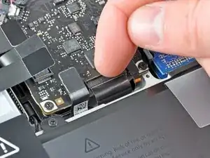
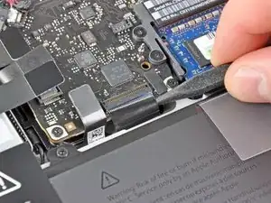
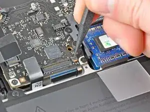
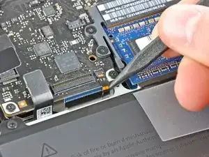
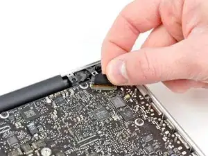
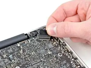
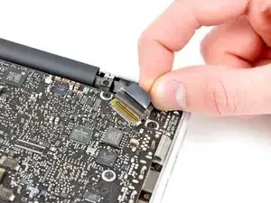
Pull the right speaker/subwoofer cable upward to lift the connector out of its socket on the logic board.
-
-
-
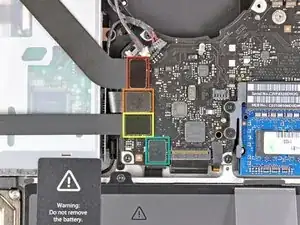
Disconnect the following four cables:
-
AirPort/Bluetooth cable
-
Optical drive cable
-
Hard drive cable
-
Trackpad cable
-
-
-
Use your fingernail to flip up the retaining flap on the keyboard ribbon cable ZIF socket.
-
Use the tip of a spudger to pull the keyboard ribbon cable out of its socket.
-
-
-
If present, remove the small strip of black tape covering the keyboard backlight cable socket.
-
-
-
Use the tip of a spudger or your fingernail to flip up the retaining flap on the keyboard backlight ribbon cable ZIF socket.
-
Pull the keyboard backlight ribbon cable out of its socket.
-
-
-
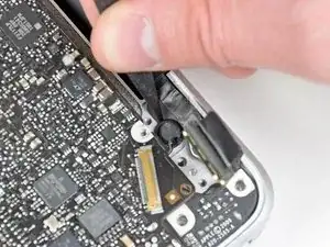
Use the flat end of a spudger to pry the sleep sensor/battery indicator connector up from its socket on the logic board.
-
-
-
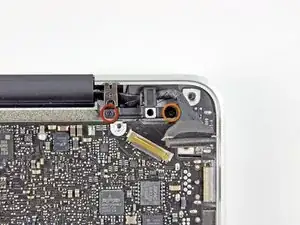
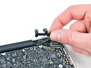
Grab the plastic pull tab secured to the display data cable lock and rotate it toward the DC-In side of the computer.
-
Pull the display data cable straight out of its socket on the logic board.
-
-
-
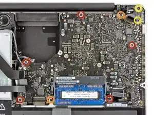
Remove the following nine screws:
-
Five 3.6 mm T6 Torx screws
-
Two 4.3 mm T6 Torx screws
-
Two 7.2 mm T6 Torx screws
-
Five 3.0 mm T6 screws
-
Two 3.6 mm T6 screws
-
Two 6.7 mm T6 screws
-
-
-
Remove the following two screws:
-
One 8.6 mm Phillips screw
-
One 5.5 mm Phillips screw
-
Remove the display data cable retainer from the upper case.
-
-
-
Use the tip of a spudger to gently peel the microphone off the adhesive securing it to the upper case.
-
-
-
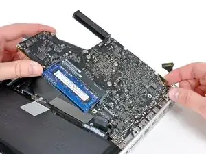
Minding the many connectors near its edges, lift the logic board from the end nearest the optical drive.
-
Without flexing the board, maneuver it out of the upper case, minding the flexible connection to the DC-In board that may get caught in the upper case.
-
Remove the logic board.
-
To reassemble your device, follow these instructions in reverse order.

One comment
If I have a MacBook Pro 13’’ A1278 Mid 2012 with i5 2.5GHz logic board, am I able to put a 2.3 GHz i5 A1278 early 2011 macbook pro logic board onto the Mid 2012 macbook pro?
Sara -
Reminder: When replacing the cable the connector should be placed in from above. This fooled me and I damaged the seat a bit, but not enough to prevent proper connection.
Lee Hughart -
Excellent guide, I feel this bit could be clearer tho. As it is a socket like a fan connector.
Mine had a foam pad on the top like the other lift-up connections and I’ve accidentally taken the socket off.
So just to be aware if your mac has the foam pad on top of this connection.
acupton86 -
I’ve broken the connector of the speaker (on the logic board) by installing it in the wrong way.
Now, I ordered the connector from aliexpress, and have to do some micro soldering and hopefully it’ll work.
Be careful guys
iAziz -
This one took me a moment to figure out. I also have the foam pad and couldn't see where the socket begins. Use the flat end of the spudger and go underneath the red/black cable part close to the socket, then slowly lift it up until it loosens a little, then do the same on the other side.
Chris -