Introduction
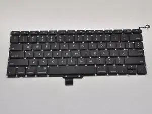
Use this guide to replace just your keyboard, not the complete top case.
Replacing the keyboard requires the removal of nearly every component in your MacBook Pro. Follow steps 1 - 36 of the MacBook Pro 13" Unibody Mid 2012 Upper Case Replacement guide.
You will also need to transfer your old keyboard backlight over to your new keyboard (if it did not come with your new keyboard).
-
-
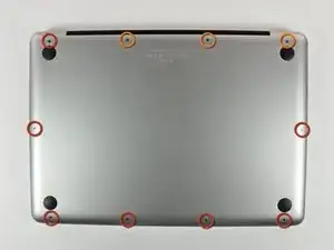
Remove the following 10 screws securing the lower case to the MacBook Pro 13" Unibody:
-
Seven 3 mm Phillips screws.
-
Three 13.5 mm Phillips screws.
-
-
-
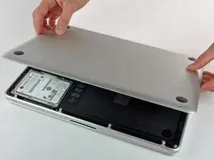
Slightly lift the lower case and push it toward the rear of the computer to free the mounting tabs.
-
-
-
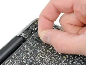
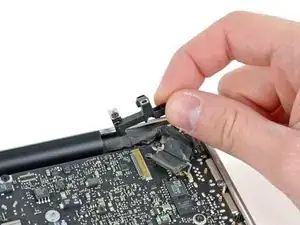
Grab the plastic pull tab secured to the display data cable lock and rotate it toward the DC-In side of the computer.
-
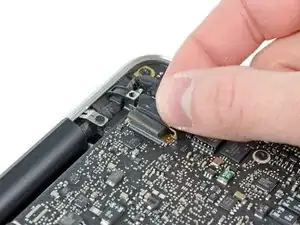
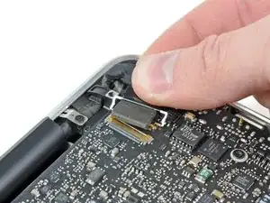
Gently pull the display data cable connector away parallel to the board.
-
-
-
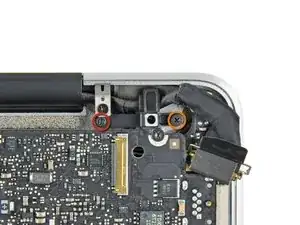
Remove the following two screws securing the display data cable bracket to the upper case:
-
One 8.6 mm Phillips
-
One 5.6 mm Phillips
-
Lift the display data cable bracket out of the upper case.
-
-
-
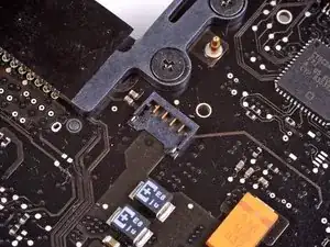
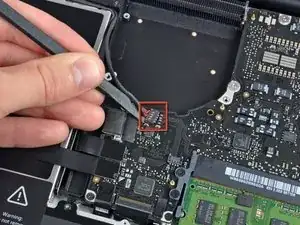
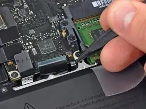
Use the flat end of a spudger to pry the subwoofer and right speaker connector up off the logic board.
-
-
-
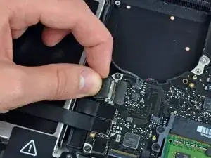
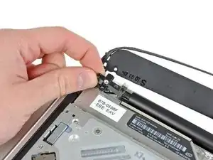
Pull the camera cable connector toward the optical drive to disconnect it from the logic board.
-
-
-
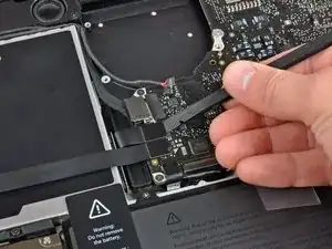
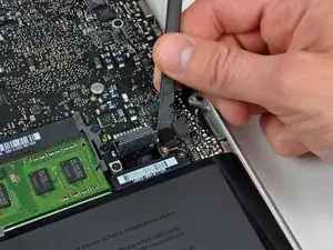
Use the flat end of a spudger to pry the optical drive, hard drive, and trackpad cable connectors up off the logic board.
-
-
-
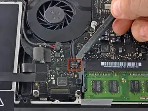
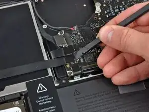
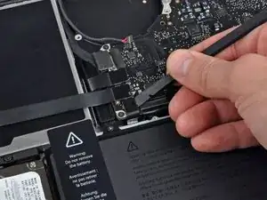
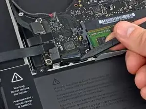
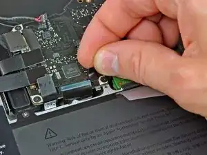
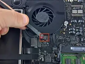
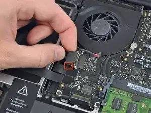
Use your fingernail or the tip of a spudger to flip up the cable retaining flap on the ZIF socket for the keyboard ribbon cable.
-
Use your spudger to slide the keyboard ribbon cable out of its socket.
-
-
-
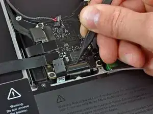
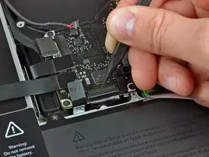
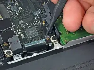
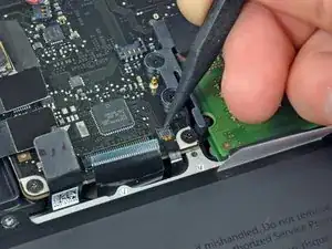
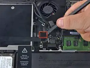
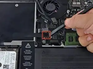
Use the tip of a spudger to flip up the cable retaining flap on the ZIF socket for the keyboard backlight ribbon cable.
-
Use your spudger to slide the keyboard backlight ribbon cable out of its socket.
-
-
-
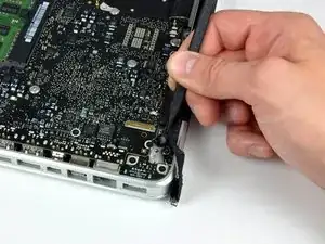
Use the flat end of a spudger to pry the battery indicator cable connector up off the logic board.
-
-
-
Use the tip of a spudger to pry the microphone off the adhesive attaching it to the upper case.
-
-
-
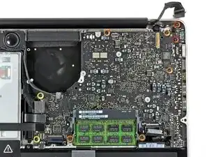
Remove the following screws:
-
Two 7 mm T6 Torx screws from the DC-In board
-
Five 3.3 mm T6 Torx screws
-
Two 4 mm T6 Torx screws
-
-
-
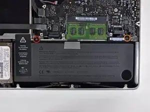
Remove the following Tri-point screws securing the battery to the upper case:
-
One 5.5 mm Tri-point screw
-
One 13.5 mm Tri-point screw
-
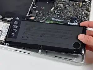
Lift the battery out of the upper case.
-
-
-
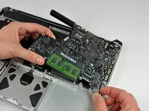
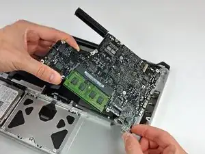
Lift the logic board from its left edge and raise it until the ports clear the side of the upper case.
-
Pull the logic board away from the side of the upper case and remove it, minding the DC-In board that may get caught.
-
-
-
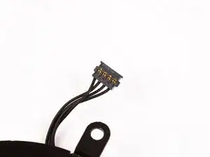
Remove the soft padding that may be on top and gently pull the connector up out of its socket on the logic board.
-
-
-
Pull the camera cable connector toward the optical drive to disconnect it from the logic board.
-
-
-
Use the flat end of a spudger to pry the optical drive connector straight up off the logic board.
-
-
-
Use the flat end of a spudger to pry the hard drive connector straight up off the logic board.
-
-
-
Remove the following screws securing the subwoofer to the upper case:
-
One 3.8 mm Phillips screw
-
One 5 mm Phillips screw
-
-
-
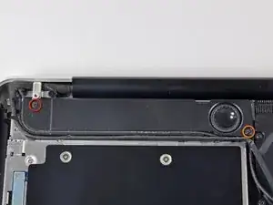
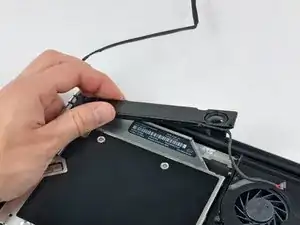
Remove the two 10 mm Phillips screws securing the camera cable bracket to the upper case.
-
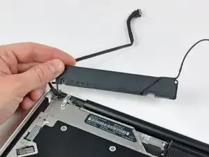
Lift the camera cable bracket out of the upper case.
-
-
-
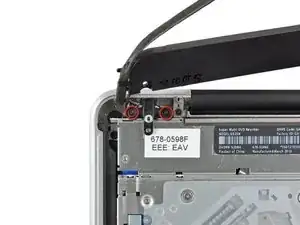
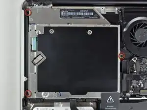
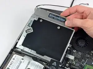
Remove the three 2.5 mm Phillips screws securing the optical drive to the upper case.
-
Lift the optical drive from its right edge and pull it out of the computer.
-
-
-
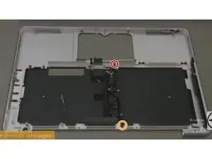
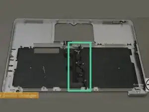
Remove the 10mm phillips #00 screw.
-
Remove the 5mm phillips #00 screw.
-
Remove and set aside the centre bracket.
-
-
-
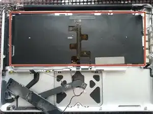
Carefully peel the black keyboard backlight from the upper case and remove it.
-
Slide a spudger under the bottom right corner and slide the spudger up the right hand side of the backlight.
-
Once you have the right hand side of the backlight loose, you can then use your fingers to gently peel the backlight from the keyboard.
-
-
-
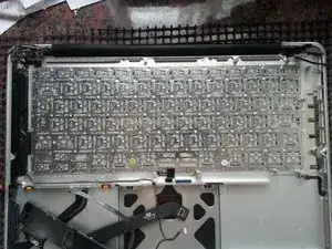
Remove the following screws:
-
Two 3 mm PH00 screws from the power button.
-
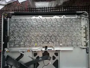
Sixty-seven 2mm PH000 screws from the keyboard.
-
Gently lift out the keyboard (and the attached power button).
-
To reassemble your device, follow these instructions in reverse order.

59 comments
Having just done this - successfully, I might add - I need to make this guide a little more clear:
Step 1: open the case. See every other tear down for the screw count.
Step 1A: remove the battery connection.
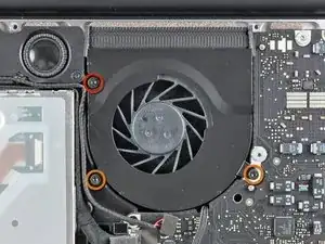
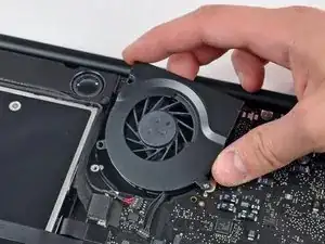
Step 2/3: remove the fan as instructed.
Step 3A: remove the optical drive. See the relevant tear down guide for specifics.
Step 3B: remove all of the connecters to the logic board: keyboard, backlight, trackpad, fan, speaker/subwoofer, battery status indicator, hard drive, optical drive, camera, display. See the logic board removal guide for more info.
Step 3C: remove the screws holding the DC-in board and the logic board. Remove the logic board.
The remaining steps are pretty OK. Buy a new backlight and diffuser panel along with your new KB.
This guide is not very good at all... terrible actually. It misses so many steps!
mark -
I successfully completed this yesterday. Having never done Mac repairs myself the difficulty level made me nervous, however don't be afraid to give it a go! There are lots of little screws and parts but its not hard, more fiddly.
In addition to the tools here consider getting some kind of segmented box or little containers to keep all the screws separate. Also when I opened it up my logic board was filthy with dust! Keep a microfiber cloth and perhaps a soft brush around the clean a little as you go.
Andi -
Where do you purchase the 13" Macbook / Macbook Pro (2009-2012) Keyboard? I can see the uppercase is for sale, but the guide is for just replacing the keyboard.
Compare the short screws carefully before reinstalling them. The shouldered screws go in the holes on the front edge.
David Kilbridge -
Before I started removing any screws I took a piece of paper and drew the bottom of the laptop and put a piece of double-sided tape in the spot where each screw goes. That way when I took out the screws, I could put them on the tape so I knew exactly which screw went in which spot. I did the same thing for dismantling the inside on another sheet of paper, then a third sheet for the screen after getting the front glass off.
mastover -
I use a similar technique: I print out the iFixit manual for the job, and Scotch-tape down the screws/brackets/cables I remove at each step next to the component descriptions. That way, when I'm reassembling, the bits are taped right next to the photo of where they came from.
adlerpe -
That's exactly what I do for all my repairs! It's the best way to keep track of all of the parts ' original location and to make sure that you don't miss any parts during reassembly.
joyitsjennie -
Great idea and one I use often
Thomas Overstreet -
Excellent idea! Thanks for sharing it here.
Laura Sharkey -
I used a 00 that fit but the screws were very tight so I used a tiny paintbrush with some wd40 on it and put it around the edges of the screws. Worked like a charm
valentinedhdh -
I use a magnetic mat and place the screws in order on that :)
Cary B -