Introduction
-
-
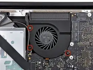
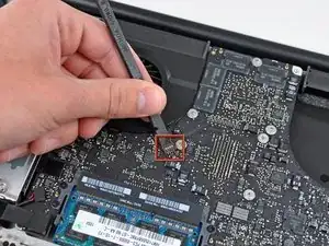
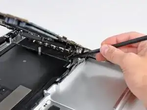
Use the flat end of a spudger to pry the right fan connector up out of its socket on the logic board.
-
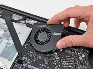
Remove the right fan from the upper case.
-
-
-
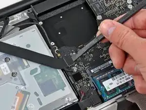
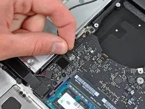
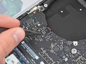
Use the flat end of a spudger to pry the AirPort / Bluetooth ribbon cable up off its socket on the logic board.
-
-
-
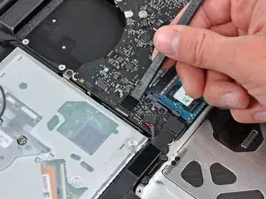
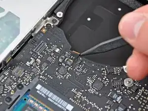
Use the flat end of a spudger to pry the optical drive cable connector up from the logic board.
-
-
-
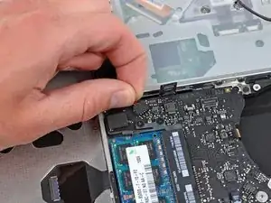
Carefully pull the subwoofer/right speaker cable up to lift its connector out of its socket on the logic board.
-
-
-
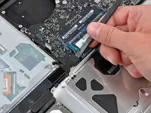
Use the flat end of a spudger to pry the hard drive cable connector up out of its socket on the logic board.
-
-
-
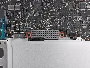
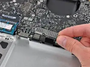
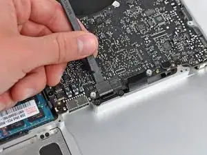
Remove the two short Phillips screws securing the small EMI shield to the logic board.
-
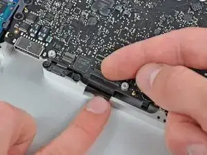
Remove the EMI shield from the logic board.
-
-
-
Use the flat end of a spudger to pry the trackpad cable connector up out of its socket on the logic board.
-
-
-
Use your fingernail to carefully flip up the keyboard ribbon cable retaining flap.
-
Use the tip of a spudger to pull the keyboard ribbon cable straight out of its socket.
-
-
-
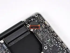
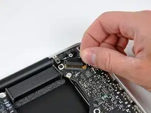
Use the flat end of a spudger to pry the battery indicator cable connector up out of its socket on the logic board.
-
-
-
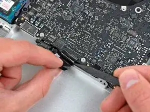
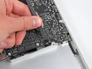
Grab the plastic pull tab secured to the display data cable lock and rotate it toward the DC-In side of the computer.
-
Pull the display data cable straight out of its socket.
-
-
-
Use the tip of a spudger or your fingernail to flip up the retaining flap on the keyboard backlight ribbon cable socket.
-
Pull the keyboard ribbon cable straight out of its socket.
-
-
-
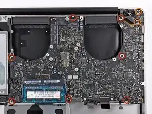
Remove the following screws:
-
Seven 3.3 mm T6 Torx screws securing the logic board to the upper case.
-
Two 8 mm T6 Torx screws securing the DC-In board to the upper case.
-
-
-
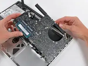
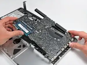
Carefully lift the logic board assembly from the left side and work it out of the upper case, minding the port side that may get caught during removal.
-
-
-
Lift the logic board enough to gain clearance and use a spudger to pry the microphone up off the upper case.
-
-
-
Slide the logic board away from the port openings and lift the assembly out of the upper case.
-

To reassemble your device, follow these instructions in reverse order.

on my screwdriver set, the T6 screw driver felt wobbly. It felt like I would strip the screw if not careful. So I used a T7 screw driver, and it was much more snug.
Bryan Chun -
Same here. T6 did not fit at all. Too small.
Bummer. Will have to screw my MBP back together and get a T7 on Monday…
Oliver Nielsen -