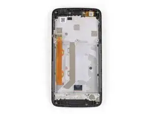
Introduction

Use this guide to replace a broken or cracked screen assembly in the Motorola Moto C Plus.

You may need need replacement adhesive to reattach components during reassembly.

  1. RKUGTbjtiQMrpt1c
    RKUGTbjtiQMrpt1c
    4wJ4m5lwg5XxKpjw
    EOVLDjWqdqGBQsxv
    • Power off your phone before beginning disassembly.

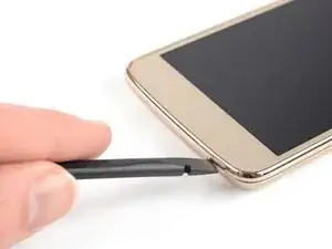
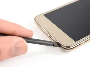
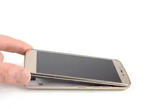
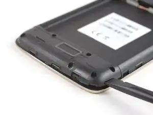
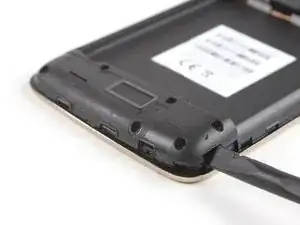
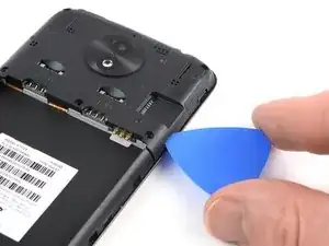
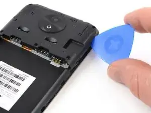
    • Insert a thumbnail, or spudger, into the notch on the bottom right to start separating the phone unit from the back cover.

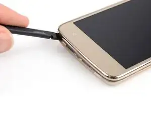
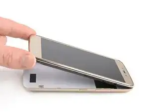
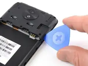
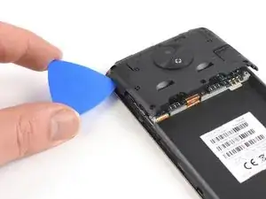
    • Move to the bottom left corner and pry the phone unit out of the back cover until you can get a good grip.

  2. TQ2xL5KeXZJadINA
    TQ2xL5KeXZJadINA
    IbmbjRYyqUcLPRLN
    • Lift the phone out of the back cover.

  3. MuDSBRGVmaw2EMlI
    MuDSBRGVmaw2EMlI
    2wHHtRyVPEnGcSXs
    ulqo1A4PRQoTUxs6
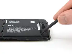
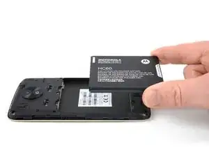
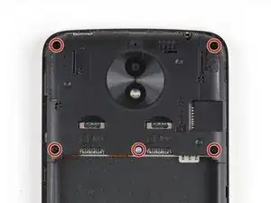
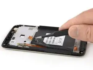
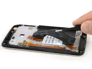
    • Use a spudger or fingernail to lift the battery starting at the notch on the bottom left.

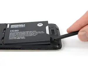
    • Lever the battery out of its recess and remove it.

  4. UVsICbYlQCSbjcma
    • Remove the six 3.1 mm Phillips #00 screws securing the daughterboard cover.

  5. 4HvHCjcgAa5QYOlf
    4HvHCjcgAa5QYOlf
    tKyaHy6qQUmAZTtH
    Rt5Y6WKmJdYSmVqi
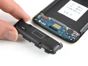
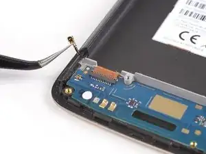
    • Apply a spudger to the right side of the daughterboard cover.

    • Twist the spudger sideways to pry up the daughterboard cover until you get a good grip.

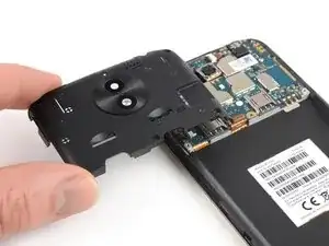
    • Remove the daughterboard cover.

  6. 1T3YIBT3Z2GOxraB
    • Remove the five 3.1 mm long Phillips #00 screws.

  7. ucrtwfRErWVe1CSg
    ucrtwfRErWVe1CSg
    OodjeHsVXTnIXyIM
    y35MjZjNXkCrdtCj
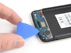
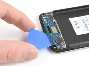
    • Apply an opening pick to the bottom right corner of the motherboard cover.

    • Twist the opening pick to free the motherboard cover out of the plastic clamps on the right side of the phone.

  8. dCrsSlAymwQK6BEC
    dCrsSlAymwQK6BEC
    xqykaOOy4Lt3LEoG
    • Repeat the previous step on the left side of the motherboard cover to free it out of the plastic clamps.

    • Pry up the motherboard cover until you can get a good grip.

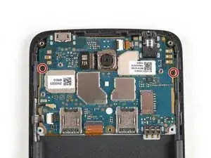
    • Remove the motherboard cover.

    Where can I buy this Motherboard?

    Rain Nier -

  9. ufltRQewlk3mFEoG
    • Remove the two 3.2 mm Phillips #00 screws securing the motherboard.

  10. kyCmoq1JU6XOPSXP
    kyCmoq1JU6XOPSXP
    1SNBEsIY6RYd51MO
    • Use the tip of a spudger to lift the latch on the power and volume button ZIF connector.

  11. tEnEand3wZjSsi4x
    tEnEand3wZjSsi4x
    hVsPge5VQ3G1JcqV
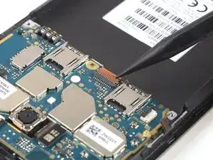
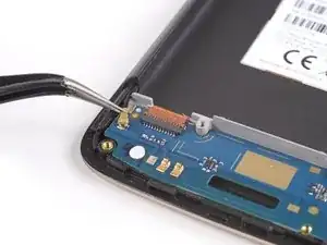
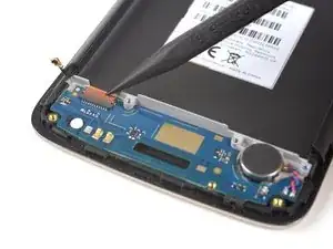
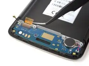
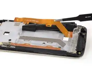
    • Use a pair of tweezers to pull the power and volume button flex cable out of the ZIF connector.

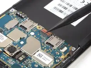
    • Fold the power and volume button flex cable out of the way.

    I have the volume of power connector broken, how can I buy one? Thanks!

    Kamel Alramahi -

  12. 1Hn5GYvGBDIHJTAD
    1Hn5GYvGBDIHJTAD
    stlM6flkTtCsosIB
    • Pry up and disconnect the antenna cable.

    • Fold the antenna cable out of the way.

  13. wiSA5FfDvX3WxKJN
    wiSA5FfDvX3WxKJN
    6lNycsaRjCUTQkYb
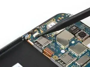
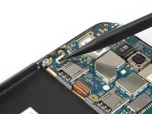
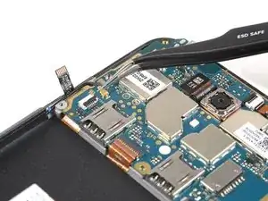
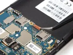
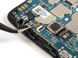
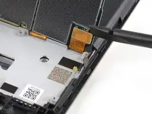
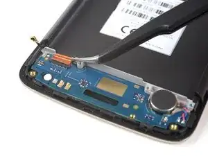
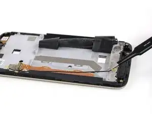
    • Use the tip of a spudger to open the interconnect cable ZIF connector by lifting the brown flap.

    • When reassembling make sure the white line on the cable aligns with the closed flap.

  14. iYP2gJ2ngUqEFy5j
    iYP2gJ2ngUqEFy5j
    LTT3vPaKRQYs3GvF
    • Use a pair of tweezers to pull the interconnect flex cable out of the ZIF connector.

  15. PmjgoO5iw4C3fHKj
    PmjgoO5iw4C3fHKj
    fPCTTKD63ehxeLoP
    • Use the tip of a spudger to open the flap of the ZIF connector next to the headphone jack.

  16. nmWraTEXrRN622xY
    nmWraTEXrRN622xY
    X1FUY4E3KySENEmV
    • Use a pair of tweezers to pull the flex cable out of the ZIF connector.

  17. TW2m3ARfnXQpN1bM
    TW2m3ARfnXQpN1bM
    IpVNknSiByAObThn
    • Don't try to remove the motherboard all the way yet. The display flex cable is still connected to its rear side.

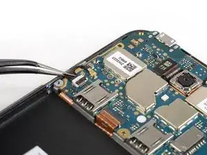
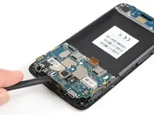
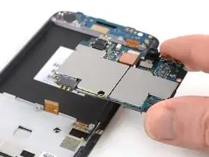
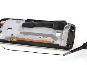
    • Use a spudger to carefully lift the motherboard until you can get a good grip. Avoid to damage the cables next to the motherboard.

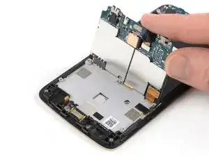
    • Lift the motherboard and fold it back until you have enough space to disconnect the display flex cable.

  18. psfEwZrZqvUPX23V
    psfEwZrZqvUPX23V
    NNOTYWROuI4N2hiQ
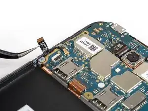
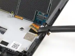
    • Use the edge of a spudger to pry up and disconnect the display flex cable from the motherboard.

  19. S6qBo45pQFwDJWsH
    • Remove the motherboard.

  20. sDwhdScnVMI5fEHC
    sDwhdScnVMI5fEHC
    d1CTfnZvyVE2jgEb
    • Disconnect the antenna cable and fold it out of the way.

  21. WIMHtMafJPWpENbM
    WIMHtMafJPWpENbM
    E4kY6WJVmOeMtAcK
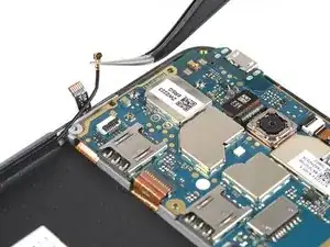
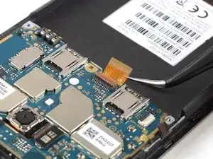
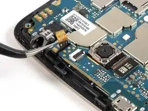
    • Use the tip of a spudger to open the brown flap of the ZIF connector that holds the interconnect cable in its place.

    • When reassembling make sure the white line on the cable aligns with the closed flap.

  22. AKsoQkDPVSNlpPfB
    AKsoQkDPVSNlpPfB
    q3bVUCafASIr2gIW
    • Use a pair of tweezers to pull the interconnect flex cable out of the ZIF connector.

  23. MSQLHDKAAPWZPn6R
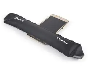
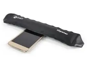
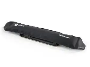
    • Prepare an iOpener and apply it to the bottom part of the display for at least two minutes to loosen the adhesive beneath the daughterboard.

  24. YRoLyXY2ZGcIy1yn
    YRoLyXY2ZGcIy1yn
    CZlTrXV542ELgM2d
    jYTSIikGXMSJJn2i
    • Apply an opening pick to the bottom edge of the daughterboard.

    • Carefully slide the opening pick under the daughterboard to cut the adhesive underneath.

    • Take care to cut the adhesive underneath the vibration motor.

    • Slide the opening pick from right to left to cut all the adhesive.

  25. crSVLEw4p5sEEK3e
    • Remove the daughterboard including the soldered-on vibration motor.

  26. ysOWmP4FbKTmrOAx
    • Use an iOpener and apply it to the top edge of the display to loosen the adhesive beneath the earpiece speaker.

  27. wJVEMLNgALXb1yul
    wJVEMLNgALXb1yul
    woJcIWJXPSpgRquD
    • Use a pair of tweezers to carefully grab and remove the earpiece speaker.

  28. CKooHZayW2QN54uy
    CKooHZayW2QN54uy
    dYLFCcZifCQUccnA
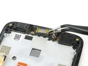
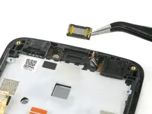
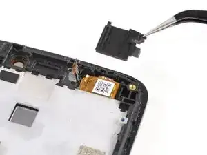
    • Use a pair of tweezers to remove the rubber headphone jack gasket in the corner of the display assembly.

  29. aDhcyRnQnKMgqHCq
    aDhcyRnQnKMgqHCq
    uYfRYaBP1XMXalYR
    • Use a pair of tweezers to remove the rubber charging port gasket.

  30. ElVLPIX3LlARUeJm
    ElVLPIX3LlARUeJm
    TBeRcYTMBRaJXWjd
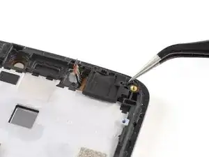
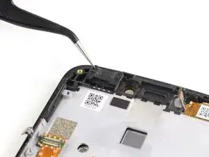
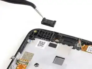
    • Use a pair of tweezers to grab and remove the microphone rubber gasket at the bottom right end of your phone.

  31. 5msgLTJKATALF1wM
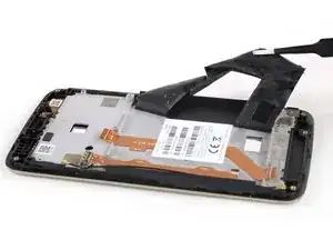
    • Use an iOpener to loosen the adhesive tape that sits on top of the interconnect and display flex cable. Apply the iOpener on the tape for at least two minutes.

  32. JEdOGKjsuSJbrYS5
    JEdOGKjsuSJbrYS5
    1FCsJj2nNAZAKmJ1
    IUZSHYR6PnYXaKQX
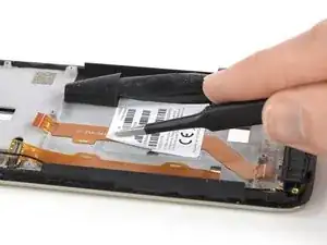
    • Use a pair of tweezers to gently peel the adhesive tape off the flex cables and fold it out of the way.

  33. CdGCvEKLIqCFCgLN
    CdGCvEKLIqCFCgLN
    o3KMtNeTlWHru6bX
    • Use a pair of tweezers to gently peel the product sticker off the interconnect cable.

    • In case you can't remove the sticker or it starts to rip apart you can re-apply an iOpener to loosen the adhesive.

  34. DAchUoJZXiDHdV6v
    DAchUoJZXiDHdV6v
    HOVV6ECnsHKOZcBK
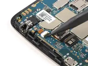
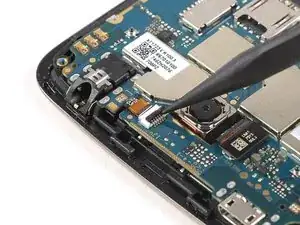
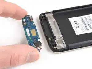
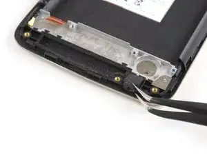
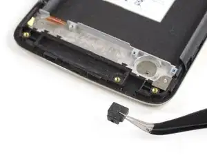
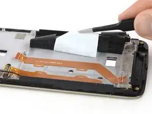
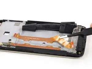
    • Use a pair of tweezers to grab and carefully peel up the interconnect flex cable.

    • Remove the interconnect flex cable.

  35. kWQLRTssiwQJP1ud
    kWQLRTssiwQJP1ud
    RnR1yVfGnRqG3d3K
    • Use a pair of tweezers to remove the antenna cable.

  36. lZDtpRQpnQHeWMFr
    • Check your replacement part for any other components that need to be transferred before reassembly.

Conclusion

To reassemble your device, follow these instructions in reverse order.

Take your e-waste to an R2 or e-Stewards certified recycler.

Repair didn’t go as planned? Check out our Answers community for troubleshooting help.

Dominik Schnabelrauch

Member since: 23/11/16

167336 Reputation

0 comments