Introduction

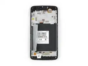
Use this guide to replace the screen of your Motorola Moto C due to a defective LCD or broken front panel.

You’ll need replacement adhesive to reattach components during reassembly.

  1. OY5FDDlnDRcGMT6E
    OY5FDDlnDRcGMT6E
    BCCiTLaWAOE4KQWP
    UFHVhRWjbUj3Msdb
    • Power off your phone before beginning disassembly.

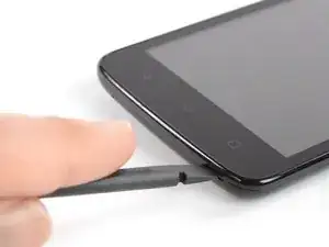
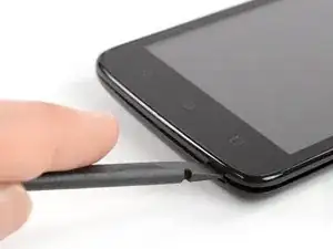
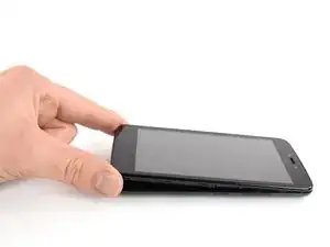
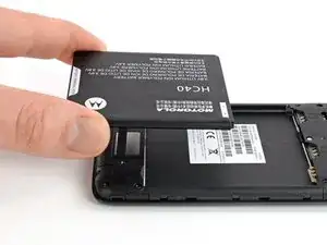
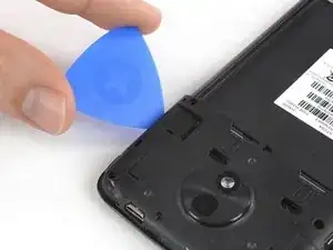
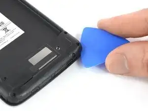
    • Insert a thumbnail, or spudger, into the notch on the bottom right corner to start separating the phone unit from the back cover.

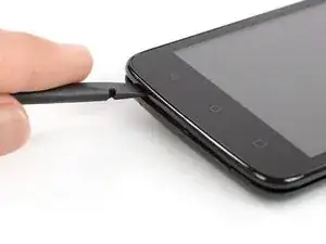
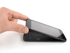
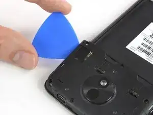
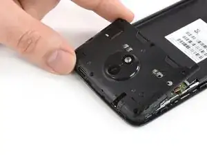
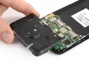
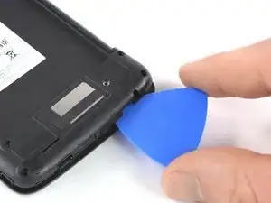
    • Move it to the bottom left corner and pry the phone unit out of the back cover until you can get a good grip.

  2. NqgP2NOoKvLv6JOv
    NqgP2NOoKvLv6JOv
    LDKeFAaRCdCygTVs
    • Lift the phone out of the back cover.

  3. Awmit2FnHmPvSBlU
    Awmit2FnHmPvSBlU
    bnKLgla6f1PI6PGl
    MEVHSPu3OToEaAq3
    • Use a finger or spudger to lever the battery out of its recess and remove it.

  4. KQNACyi4VbldJQ4U
    • Remove the six 3.5 mm long Torx T5 screws.

  5. ZRoZRQWFh3BrXuQJ
    ZRoZRQWFh3BrXuQJ
    Icj6pUMsSSxX1Rfx
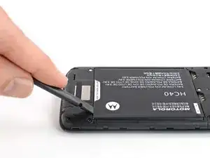
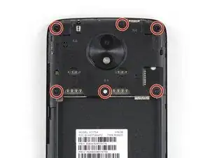
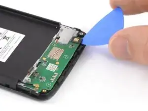
    • Insert an opening pick between the cover and the motherboard near the SIM 2 slot where the power buttons are located.

    • Slide and twist the opening pick to pry open the plastic clips securing the cover.

  6. D6REyYYLXJIAHwFS
    D6REyYYLXJIAHwFS
    QSFEWfZHYKkEn62P
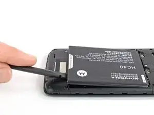
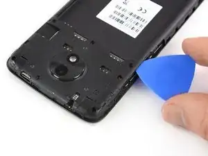
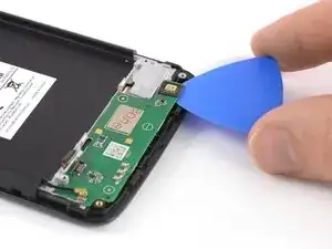
    • Slide an opening pick between the cover and the motherboard on the opposite side next to the SD card slot.

    • Twist the opening pick to pry open the plastic clips securing the cover.

  7. wUQcHtRVnNVfT3Eb
    wUQcHtRVnNVfT3Eb
    iw1Eu5hLIMRQmlMJ
    • Remove the motherboard cover.

  8. J3YR6Z6WjXbLLOgU
    • Remove the four 3.5 mm long Torx T5 screws.

    • Some screws might be covered with stickers.

  9. ZWvCCxdseexQSAUu
    ZWvCCxdseexQSAUu
    EUFxpg5qlKgaJCS5
    QU5UpuOMLwZZMZWQ
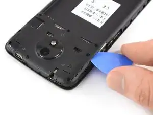
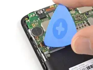
    • Apply the edge of an opening pick to the bottom right corner under the daughterboard cover.

    • Twist the opening pick to open the plastic clamps of the daughterboard cover.

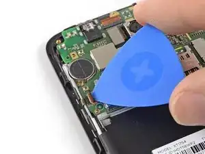
    • Slide the opening pick to the left and pry it upwards until you can get a good grip on the daughterboard cover.

  10. 6DXf1dnxoBxWnPpZ
    • Remove the daughterboard cover.

  11. eyluFPdiX2K4ZyMN
    • Remove the three 2.5 mm long T5 Torx screws.

    Rechts ist auch noch eine silberne Schraube die auf den folgenden Bildern fehlt.

    Vertumnus Gaius -

    Danke für den Hinweis. Haben es in der Anleitung aktualisiert.

    Tobias Isakeit -

  12. y1rNQmVJW3NrtHf4
    y1rNQmVJW3NrtHf4
    ToErMIYrfo3uovKV
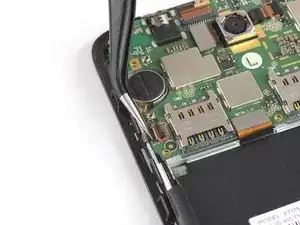
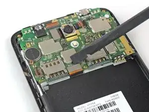
    • Use the tip of an opening pick to pry up and open the black lever of the ZIF connector located on the bottom left of the motherboard.

  13. ObpEHHMYeC2QVXA5
    ObpEHHMYeC2QVXA5
    JrI3s6oIPu3V2gIg
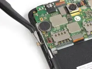
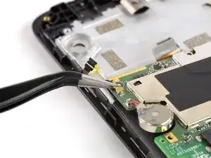
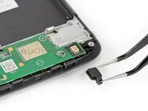
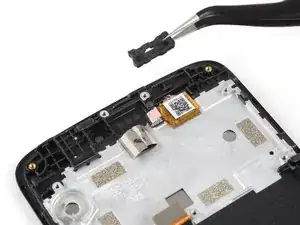
    • Use a pair of tweezers to pull the power and volume button flex cable out of the ZIF connector.

    • Fold the power and volume button flex cable out of the way.

  14. GMMPB2CH4rhYWDXf
    GMMPB2CH4rhYWDXf
    sUWjVPRMigY5NAbH
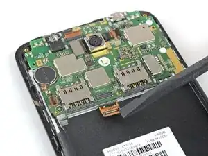
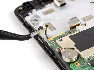
    • Use the flat end of a spudger to pry up and disconnect the display flex cable located at the bottom of the motherboard.

  15. Ze2GNxieDPb5Kp6d
    Ze2GNxieDPb5Kp6d
    RvxPlCjHythx4PBU
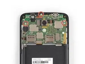
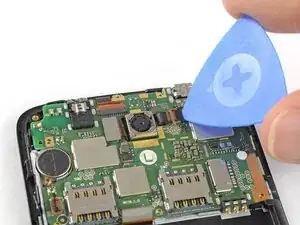
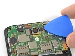
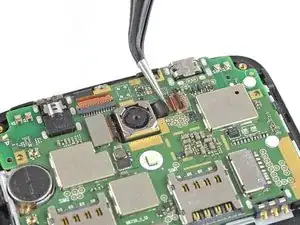
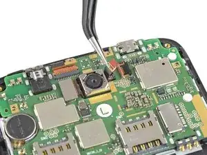
    • Use the tip of an opening pick to pry up and open the black lever of the ZIF connector located at the top of the motherboard next to the rear camera.

  16. v2GwjIIkYISTy41W
    v2GwjIIkYISTy41W
    Gulg1Pyddn26OwAV
    • Use a pair of tweezers to pull the digitizer flex cable out of the ZIF connector.

  17. XuB3FDt6DCmTVv1D
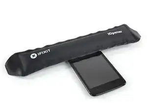
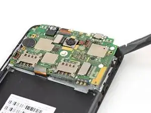
    • Prepare an iOpener and apply it to the upper half of the display for at least two minutes to loosen the adhesive beneath the vibration motor and the rear facing camera.

  18. JQJpubZkgxOYfPVh
    JQJpubZkgxOYfPVh
    Mpyq3BpIcgPCks6j
    • Don't try to remove the motherboard all the way yet. The antenna cable is still connected to its rear side.

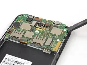
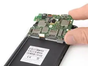
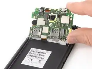
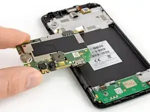
    • Use a spudger to carefully lift the motherboard until you can get a good grip. Avoid to damage the cables next to the motherboard.

  19. I3KAPFAWZpJmhGZJ
    I3KAPFAWZpJmhGZJ
    ZxyRHVPQoCNETSmQ
    H2EVGDEUBImlYfFN
    • Fold the motherboard over the battery cavity to access the coaxial cable connectors.

  20. pC3VOSoDhfVYYZDe
    pC3VOSoDhfVYYZDe
    MRjsxaSFFJYqVXEd
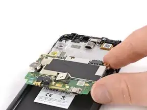
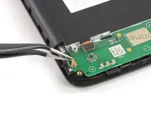
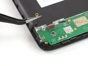
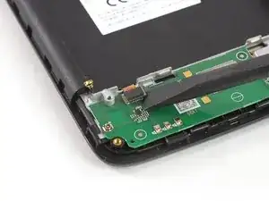
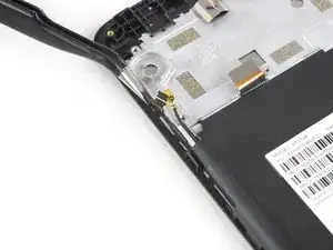
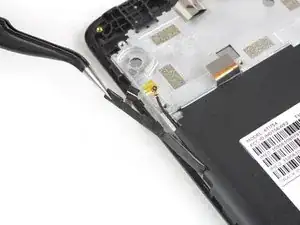
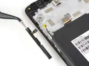
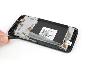
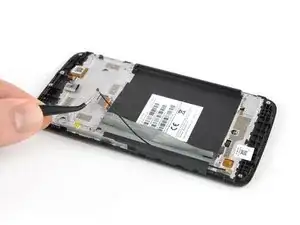
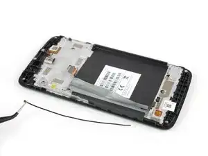
    • Use a pair of tweezers to pry up and disconnect the antenna cable from the back of the motherboard.

  21. EGX5bBkqywNKKkcs
    • Remove the motherboard.

  22. BlHPTdlHXpVhmJDr
    BlHPTdlHXpVhmJDr
    UhThxZvkJGPAen4G
    • Use a pair of tweezers to disconnect the antenna cable on the left of the daughterboard.

  23. VP2RbErjSGOY2BYI
    VP2RbErjSGOY2BYI
    m3FrScmND2CVbQK2
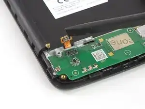
    • Use a spudger to disconnect the digitizer flex cable on the upper left of the daughterboard.

  24. pamUqTqrNrmSjTFp
    pamUqTqrNrmSjTFp
    iRTA3LFSZjujFUY2
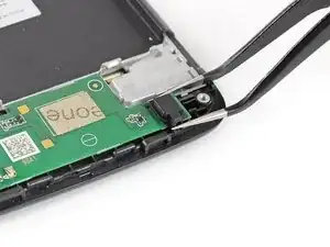
    • Use a pair of tweezers to remove the rubber gasket that covers the microphone on the bottom right of the daughterboard.

  25. R1KNKdUhrmrREjTm
    • Prepare an iOpener and apply it to the bottom part of the display for at least two minutes to loosen the adhesive beneath the daughterboard.

  26. 4YqP4j6duWUarDZx
    4YqP4j6duWUarDZx
    Q6cbT2tf1NyVmnUo
    61uJWq4iQHCkxeMY
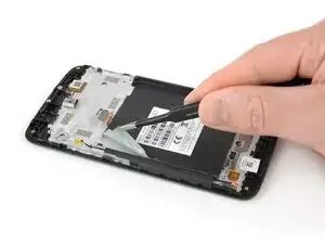
    • Apply an opening pick to the bottom right corner of the daughterboard.

    • Carefully slide the opening pick under the daughterboard to cut the adhesive underneath.

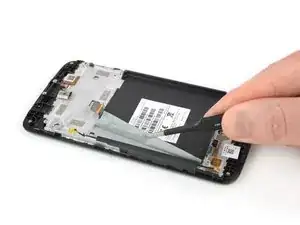
    • Slide the opening pick from right to left to cut all the adhesive.

  27. O5JRjQJ2NJXZNdNm
    O5JRjQJ2NJXZNdNm
    NASlneVcG14EBpl5
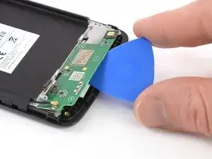
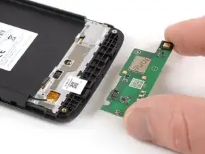
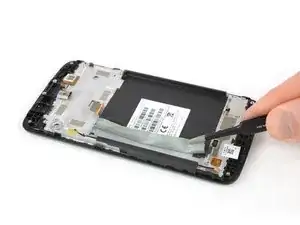
    • Twist the opening pick to lift the daughterboard until you can get a good grip.

    • Remove the daughterboard.

  28. LDPp5YrE3ZxuUsNV
    LDPp5YrE3ZxuUsNV
    K3ORODha3LOyApuD
    • Remove the ear piece speaker.

    • When reassembling, be sure to properly orient the earpiece speaker such that the gold contacts are pointing away from the top edge.

  29. e2J5YiSBAVZ36MJZ
    e2J5YiSBAVZ36MJZ
    jyRgihD3TX4MtgCS
    • Use a pair of tweezers to grab and remove the charging port rubber gasket.

  30. gYQcRacndkPFnS1h
    gYQcRacndkPFnS1h
    kbHLrHHuS4isPSOo
    RVwGZdtr2MXHutV2
    • Use a pair of tweezers to gently peel off and remove the power and volume buttons.

  31. oEQCqjwhL116EGWU
    • Prepare an iOpener and apply it for at least two minutes on the back of the phone to loosen the adhesive tape that sits on top of the display flex cable.

  32. rn53ngLrUBiMRq2v
    rn53ngLrUBiMRq2v
    VdGDSsLTwu6tQbO3
    CqABRx2xgsHmAE2y
    • Use a pair of tweezers to peel the adhesive tape off the left side where the antenna cable runs and fold it out of the way.

  33. UhpKQwnYG6VKPjwa
    UhpKQwnYG6VKPjwa
    CNm1X1KXRTddMSuC
    SJTkO3T6tO1CRZlQ
    • Use a pair of tweezers to pull the antenna cable out of its routing and remove it.

  34. ddctGFLqFZhH5UOC
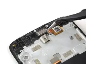
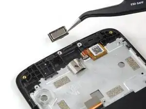
    • Check your replacement part for any other components that need to be transferred before reassembly.

    • Maybe you also want to transfer the white label with the serial number and IMEI number on it.

Conclusion

To reassemble your device, follow these instructions in reverse order.

Take your e-waste to an R2 or e-Stewards certified recycler.

Repair didn’t go as planned? Check out our Answers community for troubleshooting help.

Dominik Schnabelrauch

Member since: 23/11/16

167336 Reputation

0 comments