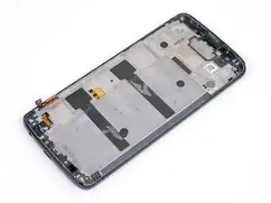
Introduction
Use this guide to replace the screen assembly on your Moto G6 Plus, including the midframe which is glued to the display.
Make sure your replacement part includes both the display and the midframe—this guide does not cover separating the display from the midframe.
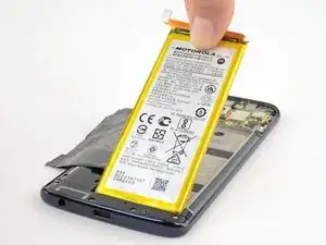
This procedure involves removing the battery, which should not be reused as it may be damaged during removal. Make sure to reassemble the phone with a new battery.
-
-
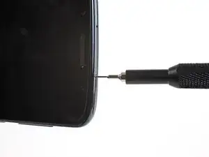
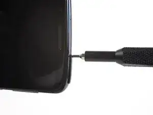
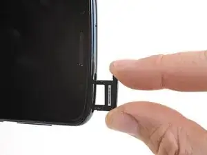
Insert a paperclip or SIM card eject tool into the small hole in the SIM card tray on the right side of the top edge of the phone.
-
Press the tool into the hole to eject the tray.
-
-
-
If possible, drain the battery before disassembly. When the battery is charged, there's increased risk of a dangerous thermal event if the battery is overheated or damaged during repairs.
-
If the rear glass is cracked, completely cover it with packing tape to contain the glass shards and avoid injury.
-
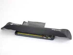
Prepare an iOpener and heat the back of the phone along its bottom edge for about two minutes, or until it's slightly too hot to touch. This will help soften the adhesive securing the rear glass.
-
-
-
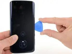
Apply a suction cup to the bottom edge of the rear glass.
-
Pull up on the suction cup with firm, constant pressure to create a slight gap between the rear glass and the case.
-
If you have trouble, apply more heat to further soften the adhesive, and try again. The adhesive cools quickly, so you may need to heat it repeatedly.
-
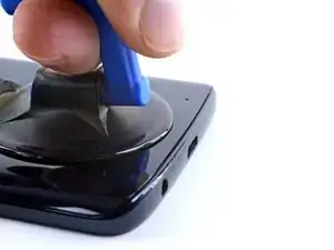
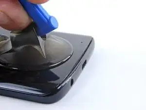
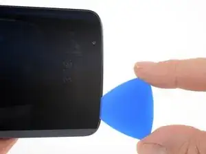
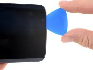
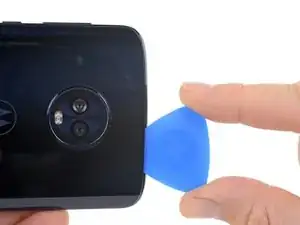
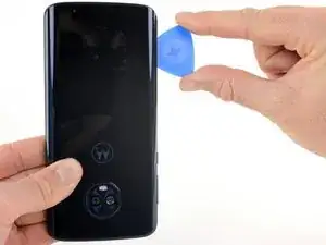
Insert an opening pick into the gap you created under the rear glass.
-
-
-
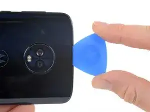
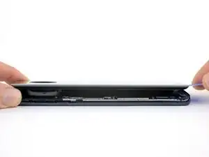
Slide the pick all along the bottom edge of the phone to slice through the adhesive securing the rear glass.
-
-
-
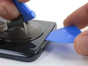
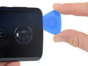
Slide the pick all along the top edge of the phone to slice through the adhesive securing the rear glass.
-
-
-
If the glass remains stuck, re-heat and slice the adhesive repeatedly as needed.
-
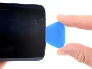
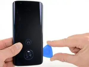
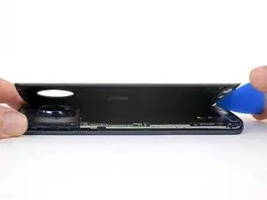
Lift the rear glass carefully, making sure it's fully separated from any adhesive.
-
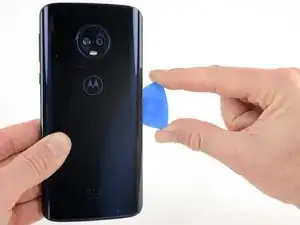
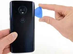
Remove the rear glass.
-
-
-
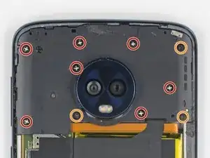
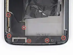
Use a Phillips driver to remove ten screws securing the upper plastic cover.
-
Seven 3.2 mm-long screws
-
Three 2.7 mm-long screws
-
-
-
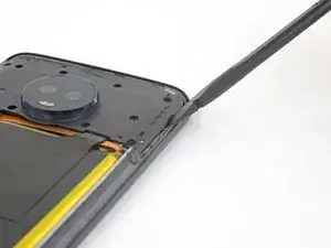
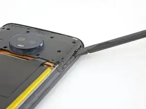
Insert the flat end of a spudger into the notch on the right edge of the upper plastic cover.
-
Pry up with the spudger to lift the edge of the upper cover and release the clips holding the cover down.
-
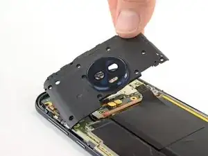
Remove the upper plastic cover.
-
-
-
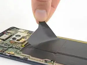
Very carefully peel up all the black stickers covering the battery.
-
If possible, keep the tape intact so it can be reused during reassembly.
-
-
-
Prepare an iOpener and apply it directly to the battery for at least two minutes. Reheat and reapply the iOpener as needed.
-
Alternatively, apply some isopropyl alcohol under each corner of the battery and allow it to penetrate for several minutes to help weaken the adhesive.
-
-
-
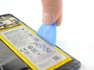
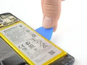
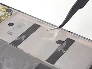
Use an opening pick to steadily pry the battery up, starting from the right edge of the battery.
-
-
-
Use a Phillips #000 driver to remove six 3.2 mm-long screws securing the lower plastic cover.
-
-
-
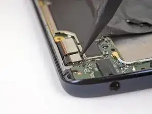
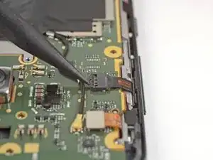
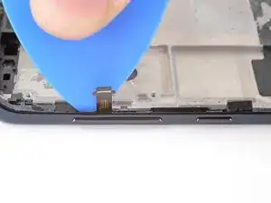
Use the point of a spudger to pry the digitizer connecter straight up and out of its socket on the motherboard.
-
-
-
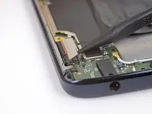
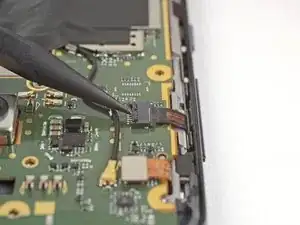
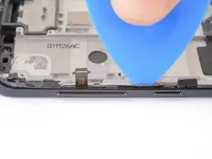
Use the point of a spudger to pry the LCD connector straight up and out of its socket on the motherboard.
-
-
-
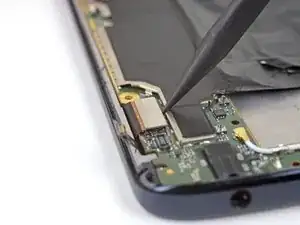
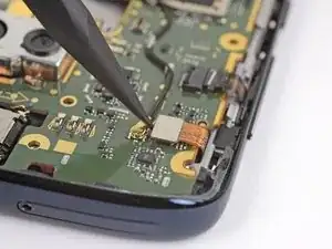
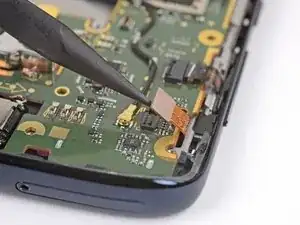
Use the point of a spudger to flip up the small locking flap on the ZIF connector on the motherboard.
-
Gently pull the ribbon cable out of its socket.
-
-
-
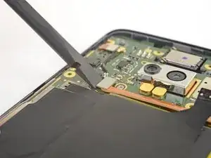
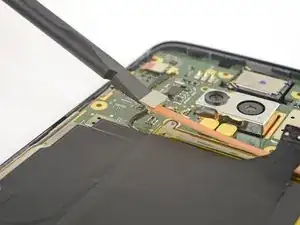
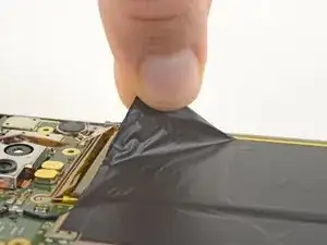
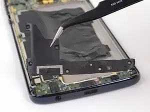
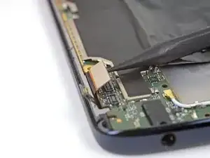
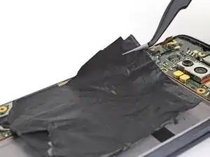
Gently peel away the large black sticker covering the middle of the motherboard.
-
If possible, keep the tape intact so it can be reused during reassembly.
-
-
-
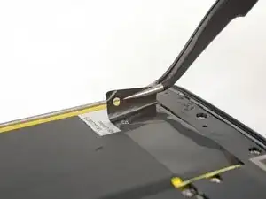
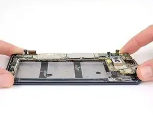
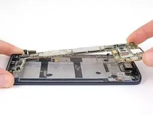
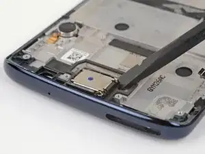
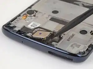
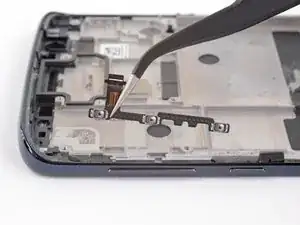
Carefully lift the top of the motherboard, keeping it clear of any cables and connectors.
-
Slide the motherboard toward the top of the phone to remove it from the midframe.
-
-
-
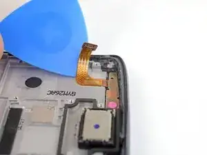
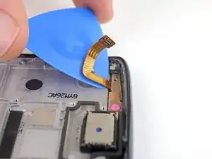
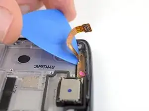
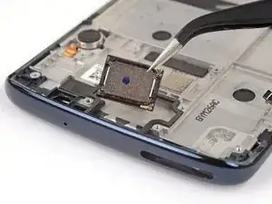
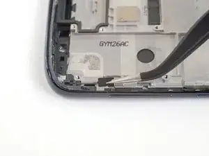
Gently slide an opening pick under the front-facing sensor cable to slice through the adhesive holding it to the midframe.
-
Use the opening pick to carefully pry the front-facing sensor array away from the midframe.
-
-
-
Use the flat end of a spudger to pry up one corner of the earpiece speaker.
-
Continue lifting the speaker until it is completely separated from its adhesive.
-
Remove the earpiece speaker.
-
-
-
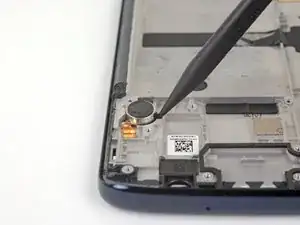
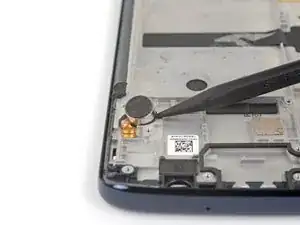
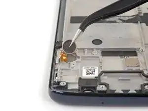
Use the point of a spudger to pry the vibrator motor and its connector up from the adhesive securing them to the midframe.
-
Remove the vibrator motor.
-
-
-
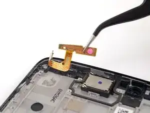
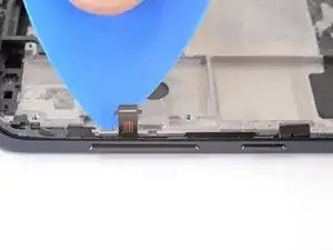
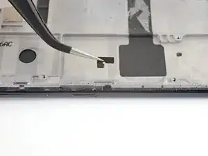
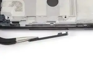
Insert an opening pick between the power and volume button circuit board and the midframe.
-
Slide the pick behind the circuit board, across the whole board, to separate it from the adhesive securing it to the midframe.
-
-
-
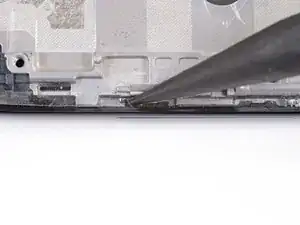
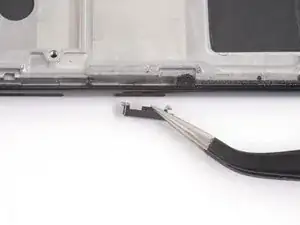
Use tweezers to carefully pull the volume and power button circuit board out of its slot. If it's difficult to remove, make sure you've sliced through all its adhesive.
-
-
-
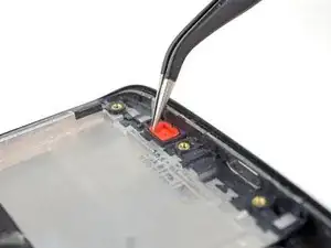
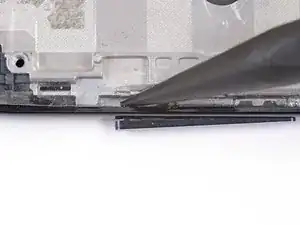
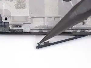
Use tweezers to lift the two black retaining brackets on either end of the volume and power buttons straight up and remove them from the phone.
-
-
-
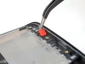
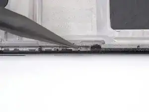
Use the point of a spudger to push against the back of the volume button cover, on the upper end of the cover, so that the upper end of the cover slides out of the phone.
-
-
-
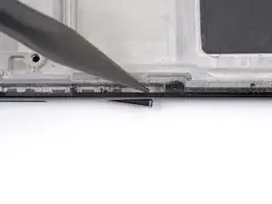
Use the point of a spudger to push against the back of the power button cover, on the lower end of the cover, so that the lower end of the cover slides out of the phone.
-
-
-
Only the screen assembly remains.
-
Compare your new replacement part to the original part—you may need to transfer remaining components or remove adhesive backings from the new part before installing.
-


To reassemble your device, follow the above steps in reverse order.
Take your e-waste to an R2 or e-Stewards certified recycler.
Repair didn’t go as planned? Check out our Answers community for troubleshooting help.