Introduction

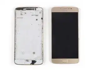
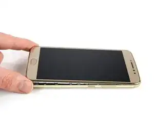
Use this guide to remove the LCD and digitizer of your Motorola Moto E4 Plus.

Before disassembling your phone, discharge the battery below 25%. The battery can catch fire and/or explode if accidentally punctured, but the chances of that happening are much lower if discharged.

This guide replaces only the display while leaving the original frame and battery in place. Some replacement screens for this phone come pre-installed on a new frame (a.k.a. chassis), which requires following a very different procedure. Make sure you have the correct part before starting this guide.

  1. PCCXuPCwmVpwtTCZ
    PCCXuPCwmVpwtTCZ
    bPy2yicrAdZxADOP
    2lalNWm6HLMBs6AH
    • Power off your phone before beginning disassembly.

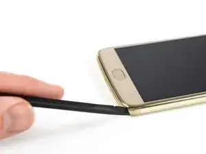
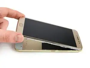
    • Insert the edge of the spudger into the notch on the bottom right corner of the phone.

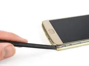
    • Twist the spudger to start releasing the back cover from the phone.

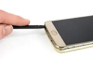
    • Slide the spudger along the bottom edge to separate the back cover from the phone.

  2. BUAOpKayenHBerHv
    BUAOpKayenHBerHv
    Hajy1vGJYVD5BJSq
    • Lift the phone unit out of the back cover.

  3. Mq2wTWMIi6bGSEX5
    • Remove the nineteen 3.2 mm long T3 screws securing the plastic midframe.

  4. FENImFKLpNmuSGRG
    FENImFKLpNmuSGRG
    oHr6G24aZv1yMCfw
    • The plastic midframe is still held in place with clips.

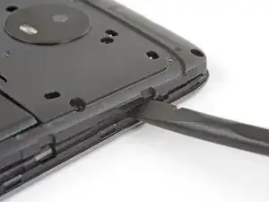
    • Insert the flat end of a spudger into the midframe seam at the bottom left corner of the phone (near the microphone hole).

    • Twist the spudger to release the plastic clip.

    • Repeat the process for the clip near the top right corner of the phone.

  5. cKwFSBqZQ2YEiVLM
    cKwFSBqZQ2YEiVLM
    aO5yK3AvuoVJTpNG
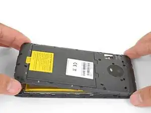
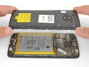
    • Lift the bottom edge of the plastic midframe upwards until the clips along the top edge release.

    • Remove the plastic midframe.

    • To reattach the plastic midframe, line up the midframe to the phone and squeeze along the edges to engage the clips.

  6. 5mx5iwONooV6ehXS
    5mx5iwONooV6ehXS
    eQtY6GOrcukID2DQ
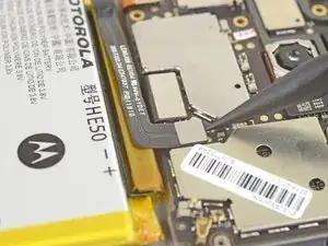
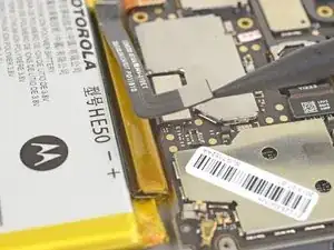
    • Use the point of a spudger to pry up and disconnect the battery connector from its motherboard socket.

  7. Vp2n52gDpDy6JlDw
    Vp2n52gDpDy6JlDw
    YDRDDuFDImyBAJbI
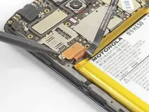
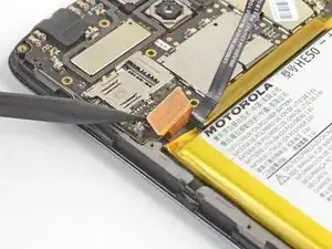
    • Use the point of a spudger to pry up and disconnect the display cable from its motherboard socket, near the bottom left corner of the motherboard.

  8. R23PlwkWLXIRNFHY
    R23PlwkWLXIRNFHY
    k1KhlLGZEcCUNRXc
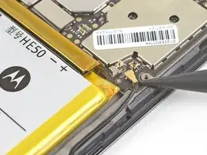
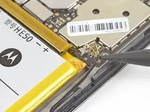
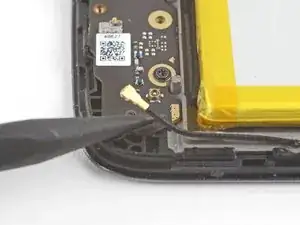
    • Use the point of a spudger to pry up and disconnect the antenna cable from its motherboard socket.

  9. vmZJyTFq5mLtIVW5
    vmZJyTFq5mLtIVW5
    ICJApQWSJfFBOaKJ
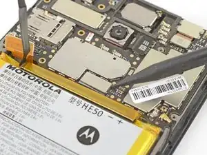
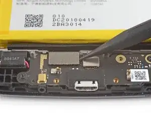
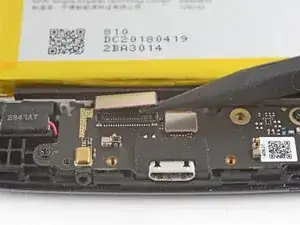
    • Use the point of a spudger to pry up and disconnect the interconnect cable from its motherboard socket.

  10. YdduRJr2cnRlEOTg
    • Remove the two black 3.2 mm long T3 screws securing the motherboard.

  11. UfdhrsPxcZXFg3pK
    UfdhrsPxcZXFg3pK
    ouvLqTRUsDvKUhRp
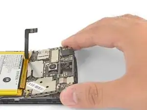
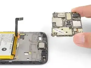
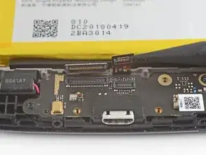
    • Grasp the motherboard by the top corners and lift it out of the phone.

    • Remove the motherboard.

  12. FATBrpLfjLt5xEbY
    FATBrpLfjLt5xEbY
    L1lSiaqRQNpqmPxg
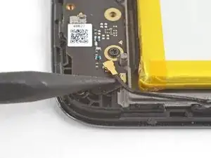
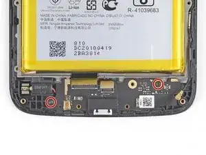
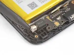
    • Use the point of a spudger to pry up and disconnect the antenna cable from its daughterboard socket.

  13. xnAYACEPiwlpQvsc
    xnAYACEPiwlpQvsc
    RbWNjxWJQsEfadXr
    oKDitDZKPFjJe1tf
    • Use the point of a spudger to pry up and disconnect the interconnect cable from its daughterboard socket.

    • Pry up and disconnect the fingerprint sensor cable next to it from the daughterboard.

  14. OV2dW1AsGepTftPD
    • Remove the two 3.2 mm long T3 screws securing the daughterboard.

  15. Me3VWHwvXpxg3Atl
    Me3VWHwvXpxg3Atl
    ZjvRn2xvsJK1C1vd
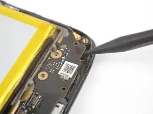
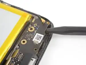
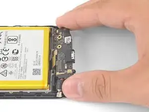
    • Insert the point of a spudger under the bottom right corner of the daughterboard and pry up to loosen the daughterboard.

  16. yvd4vQba1OVfWAhi
    yvd4vQba1OVfWAhi
    owU4yxpF5AqQE5y2
    • Insert the point of a spudger underneath the vibration motor and pry upwards to loosen it.

  17. dRZrK1lNacEAYc2D
    dRZrK1lNacEAYc2D
    vGQlVuQVTUsmhJAY
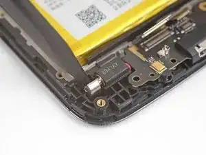
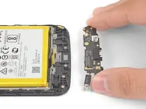
    • Grasp the daughterboard by the edges and lift it out of its recess.

    • Remove the daughterboard. The vibration motor will be attached to it.

  18. jX1hejJtrQCqyQqD
    jX1hejJtrQCqyQqD
    ImsbMGX2Y1QTimId
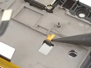
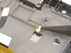
    • Use the point of a spudger to pry up and disconnect the display grounding cable from the frame.

    • When you install the replacement cable, be sure that it is properly positioned with the gold side facing up.

  19. eNtvJNvQSmPXVITa
    • Prepare an iOpener and apply it to the display for at least two minutes to loosen the adhesive underneath.

  20. WSnWQD3lhZT4rUM2
    WSnWQD3lhZT4rUM2
    KeUUplfDRGpoPdVI
    HMdJvBRck6ZMMSXB
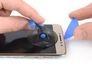
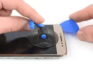
    • Once the screen is warm to the touch, apply a suction cup near the top edge of the phone below the earpiece speaker.

    • If the phone's screen is cracked, the suction cup may not stick. Try lifting it with strong tape, or superglue the suction cup in place and allow it to cure so you can proceed.

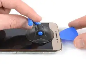
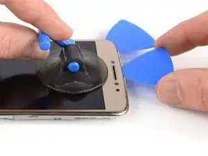
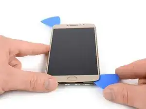
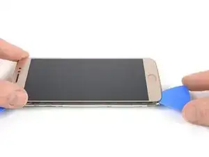
    • Pull up the suction cup, and insert the tip of an opening pick under the display where the earpiece speaker is located.

    • Slide the opening pick to the top left corner of the phone to cut the adhesive.

  21. SJxQtLNUFUP332Wa
    SJxQtLNUFUP332Wa
    3RBJZvFcRGR6yNrR
    • Insert a second opening pick and slide it to the top right corner of the phone.

  22. ga1jZMgNbuAZyyGq
    ga1jZMgNbuAZyyGq
    SoowZRFiQSVePpJ6
    yrXvF1kCEQvkOGh5
    • If cutting becomes too difficult, reheat and reapply the iOpener to the screen.

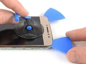
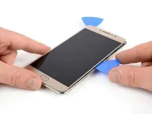
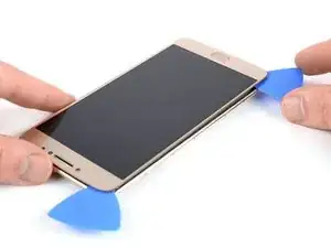
    • Slide the opening pick from the top right corner down the right edge of the phone and cut the adhesive with it.

    • While cutting, make sure the pick slides under the display panel and not just between the display and the front glass.

    • Continue sliding the opening pick around the bottom right corner of the phone.

  23. q1jamxQUWy2lMAxk
    q1jamxQUWy2lMAxk
    GXBVKBnRJFGCA2Mn
    RAVCYOYjJHqGpgoL
    • Slide the opening pick along the bottom edge of the phone and cut the adhesive.

    • Be careful around the home button, inserting only the tip of the opening pick to prevent damaging the button.

  24. Gxlq4ePuEBwPDxsZ
    Gxlq4ePuEBwPDxsZ
    cIJcXSWdpl2DAseJ
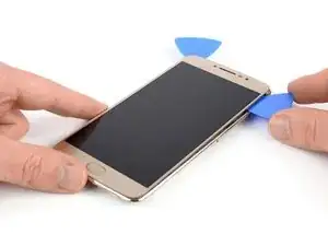
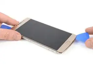
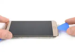
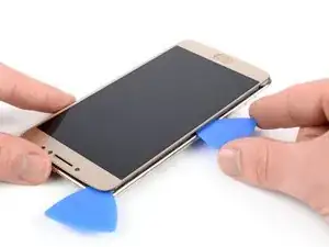
    • Repeat the previous heating and cutting procedure on the left edge of the phone to cut the remaining adhesive.

    • Don't completely remove the display yet! The fingerprint and display flex cables are still threaded through the midframe.

  25. BNW11qHThLGbRoCa
    BNW11qHThLGbRoCa
    WR4a6lPPKMEDNVbR
    13bvB6QKCx5X3BdV
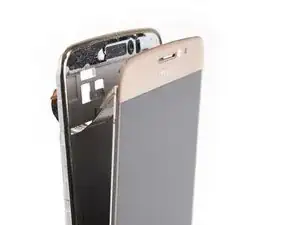
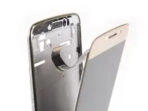
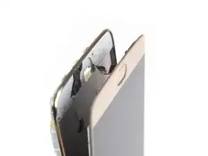
    • Carefully thread the display cable at the top and the fingerprint sensor cable on the bottom through their gaps in the midframe.

    • Remove the LCD and digitizer.

    • Remove any remaining adhesive from the midframe, and clean the glued areas with isopropyl alcohol and a lint-free cloth.

    • In case your new LCD and digitizer doesn't include the fingerprint sensor, you will need to continue with the fingerprint sensor guide to transfer it to the new LCD and digitizer.

    • Carefully compare your replacement part with your screen. You may need to transfer minor parts such as earpiece bezel to the new part.

    bonsoir j ai fait exactement comme vous dite mais pour le remontage je n ai pas l adhésif pour faire étanchéité de la vitre sur le châssis. comment faire ?

    franck souchon -

Conclusion

To reassemble your device, follow these instructions in reverse order.

If possible, turn on your phone and test your repair before installing new adhesive and resealing the phone.

Take your e-waste to an R2 or e-Stewards certified recycler.

Repair didn’t go as planned? Try some basic troubleshooting, or ask our Moto E4 Plus Answers community for help.

Arthur Shi

Member since: 03/01/18

218169 Reputation

0 comments