Introduction

Use this guide to replace a broken or defective screen assembly of your Motorola Moto E4 (XT1762). This guide can also be used to replace the screen on a Moto E4 (XT1766) with a fingerprint sensor.

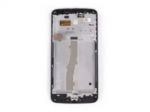
This guide shows the procedure for the screen assembly including the frame. Make sure you have the correct part before starting this guide.

You may need replacement adhesive to reattach components during reassembly.

For replacing the LCD and digitizer only use this guide.

  1. UynY2hJoXFVqfVet
    UynY2hJoXFVqfVet
    RJkQk1JxTHO4mOhC
    s3YaWwftYxyRsHTe
    • Power off your phone before beginning disassembly.

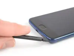
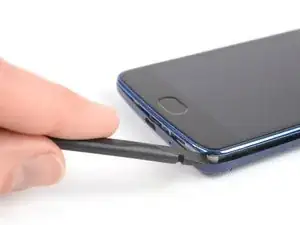
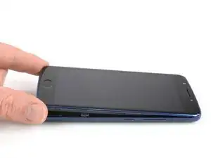
    • Insert a fingernail, or spudger, into the notch on the bottom right corner to start separating the phone unit from the back cover.

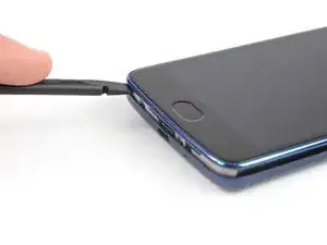
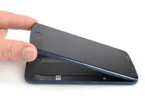
    • Move to the bottom left corner to pry the phone out of the back cover.

    I hve a question not a comment. I would like to know if this battery model will work in my moto E 4 Model # XT1775. Thank you.

    Gamaliel Gooding -

    This models battery is compatible with the Moto G4 Play, E4, and E5 Play:

    Motorola Moto G4 Play, E4, and E5 Play Battery - Genuine

    You’re probably looking for the Moto E4 Plus (XT1775) battery:

    Moto E4 Plus Battery - Genuine

    Tobias Isakeit -

    My US XT1768 did not have a notch here. I used my fingernails to pop the back cover off. Also, I followed this guide to successfully repair my US XT1768 in about 2 hrs. I’ve added a few comments below to point out the slight differences I found along the way

    Tom Bartol -

  2. w2XLjfi46aFfd1HD
    w2XLjfi46aFfd1HD
    3FblWACREvNC4yqL
    • Lift the phone out of the back cover.

  3. 4BrNvEjE6YFoNZyU
    4BrNvEjE6YFoNZyU
    P2Fo6DtC2EjFwxHv
    iYwHe4bOeNGepLDt
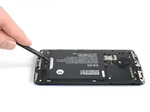
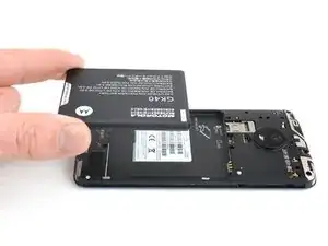
    • Use a fingernail or spudger to pry at the notch at the bottom end of the battery.

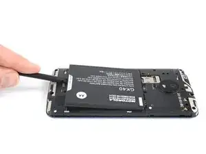
    • Lever the battery out of its recess and remove it.

  4. AM51UNXjNRiftYk6
    • Remove the six 3.3 mm long Phillips #00 screws.

  5. 6jsVTPAjR1KEOAIC
    6jsVTPAjR1KEOAIC
    kTFDnZhEFZpqMm2C
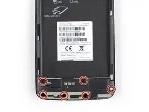
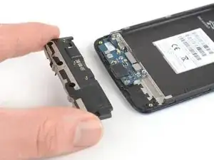
    • Insert an opening pick between the loudspeaker and the frame to pry it up by twisting the opening pick.

    • Remove the loudspeaker unit.

  6. hJlQsTC1RC6irnEB
    • Remove the seven 3.3 mm Phillips #00 screws.

    My US XT1768 has 9 screws

    Tom Bartol -

  7. MKsPcpoGS1dQY4Fc
    MKsPcpoGS1dQY4Fc
    Swbd4psdeMLxLcQV
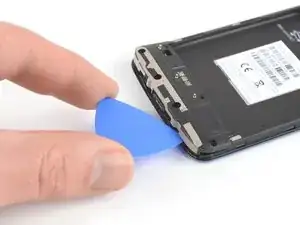
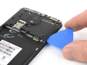
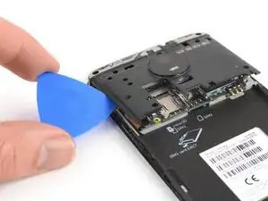
    • Insert an opening pick between the cover and the motherboard at the bottom right corner.

    • Slide the opening pick upwards to open the plastic clips.

    It was a bit tricky to pop the cover on my US XT1768 as there is a big tab near the battery compartment. Don’t force this tab. Instead, keep working on snapping the tabs loose on the headphone jack side of the cover. This worked for me.

    Tom Bartol -

  8. VvOYMQg2JcysTiQi
    VvOYMQg2JcysTiQi
    nRjVpihgSwEwsJun
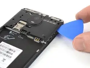
    • Insert an opening pick between the cover and the motherboard at the bottom left corner.

    • Slide the opening pick upwards to open the plastic clips.

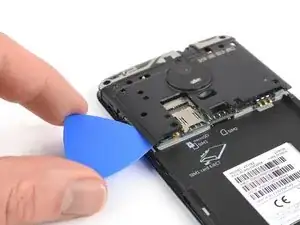
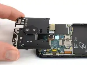
    • Pry up the motherboard cover by twisting the opening pick.

  9. g11QoOHhvGxXEvXk
    • Remove the motherboard cover.

  10. XqT6XnQXwtAkxO5x
    XqT6XnQXwtAkxO5x
    deR3MfquhSobmJoS
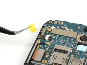
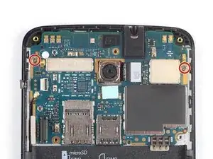
    • Use a pair of tweezers to peel off the yellow tape of the ZIF connector located on the left of the motherboard.

    My US XT1768 did not have the yellow tape.

    Tom Bartol -

  11. vLSO1gvfU4u422ZV
    vLSO1gvfU4u422ZV
    gZIFMpKa5rvUhjZj
    • Use the edge of a spudger to open the black flap of the ZIF connector.

  12. PqpVZUk1EUy6OMSF
    PqpVZUk1EUy6OMSF
    TEV1Ata5mOOWeMKH
    • Slide the volume button flex cable out of the ZIF connector to disconnect it.

  13. YymMJRCDqrmpDLox
    YymMJRCDqrmpDLox
    4CjOZIb5iQeUCemx
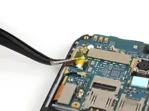
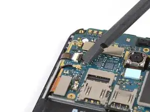
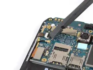
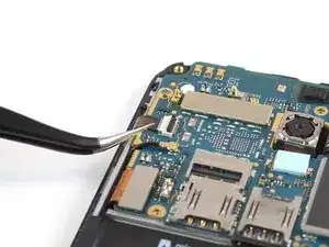
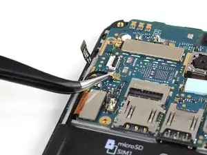
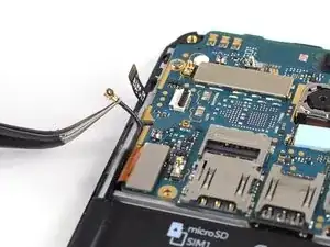
    • Use a pair of tweezers to pry up and disconnect the antenna cable located on the left of the motherboard.

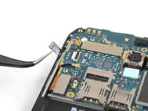
    • Fold the antenna cable out of the way.

    My US XT1768 has the antenna cable on the opposite side of the unit.

    Tom Bartol -

  14. qSGoA2WT5NQt6RcQ
    qSGoA2WT5NQt6RcQ
    GLaEAsDO3hyGi6sI
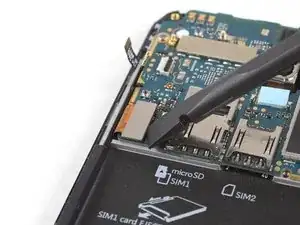
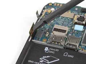
    • Use the edge of a spudger to pry up and disconnect the display flex cable located on the bottom left of the motherboard.

  15. jNaCdjKZDUylFNyA
    • Remove the two 2.9 mm long Phillips #00 screws securing the motherboard.

  16. NS2ATPs3qs2ZAZHI
    NS2ATPs3qs2ZAZHI
    nGotjJGEWNnrpxOE
    • Don't try to remove the motherboard all the way yet. The interconnect flex cable is still connected to its rear side.

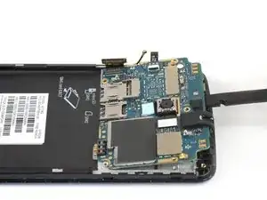
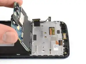
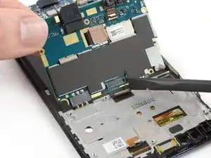
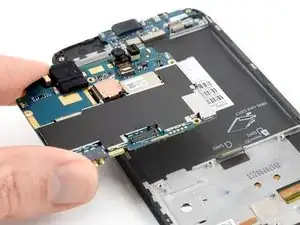
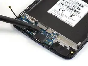
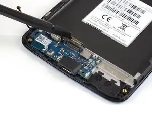
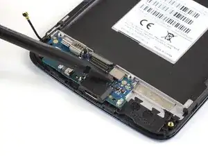
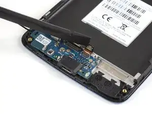
    • Use a spudger to carefully lift the motherboard from the top and fold it towards the battery compartment.

    • Be careful not to damage any components underneath the motherboard.

  17. SlsIVAOR6CMYaXYj
    SlsIVAOR6CMYaXYj
    2IuCII6Wt5yK4iqU
    Mtew6OkEDY5BXJWk
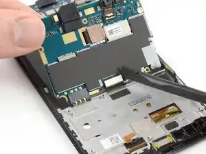
    • Use the edge of a spudger to disconnect the interconnect cable from the motherboard.

    • Remove the motherboard.

  18. AtHyVMD5CDPARjkg
    AtHyVMD5CDPARjkg
    bPup1yiXOIdXGBfk
    • Use a pair of tweezers to pry up and disconnect the antenna cable.

  19. TxRJMhSWrpimLIPm
    TxRJMhSWrpimLIPm
    YLfVgWSIpgZMZLIr
    • Use the edge of a spudger to pry up and disconnect the interconnect flex cable.

  20. NleRnVtGW4acTcOh
    NleRnVtGW4acTcOh
    Q56OgAoP4FcIcHHY
    • Use the edge of a spudger to pry up and disconnect the fingerprint sensor flex cable.

  21. cXSPnJUZPQkLxlVr
    • Remove the 2.9 mm long Phillips #00 screw securing the daughterboard.

    My US XT1768 has two screws securing the daughterboard and the board spans the full width of the case.

    Tom Bartol -

  22. Ryrv3bTekjtPZP4I
    Ryrv3bTekjtPZP4I
    EOCPDxctbCVWHZv1
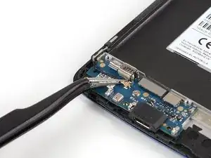
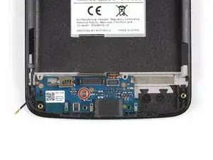
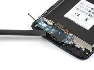
    • Pry under the bottom end of the charging board and lift it upwards.

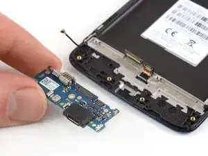
    • Remove the charging board.

    My US XT1768 has the vibrator motor not mounted on the daughterboard. Instead, the vibrator is connected by wires to the board and is secured loosely secured in a small slot in the case. Just use the tip of the spudger to pop it up out of this small slot a little at a time as you also pop of the daughterboard. Be careful not to pull on the wires.

    Tom Bartol -

  23. 1Gy5ecCs1LFpTu5g
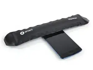
    • Apply a heated iOpener for about one minute to the upper part of the display to loosen the adhesive beneath the earpiece speaker.

  24. ubY6Hr3jrvjJYfvk
    ubY6Hr3jrvjJYfvk
    kQW6YIcVXgNbk2LA
    • Use a pair of tweezers to lift the earpiece speaker out of its recess and remove it.

    • When reassembling, be sure to properly orient the earpiece speaker such that the gold contacts are pointing away from the top edge.

    The earpiece speaker on the US XT1768 is larger and has the contact pins on the right side (viewed from the back as in the view shown here). Also there are two contact pads with textured conductive tape that need to be scavenged from the old part and applied to the replacement contact. One of these contacts the back of the camera, and the other is near the QR code sticker shown in the picture above.

    Tom Bartol -

  25. H4tSo5vTWVZI1IdW
    • Apply a heated iOpener to the left edge of the phone for about 30 seconds to loosen the adhesive beneath power and volume button unit.

  26. LVFZTTuVIhD1FB5X
    LVFZTTuVIhD1FB5X
    KYavADtLWTYpRkiv
    P1LGuTtAOjkvTT2D
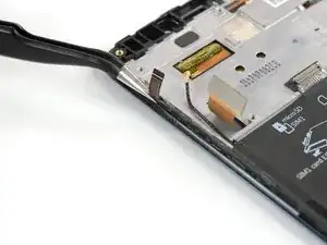
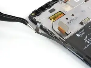
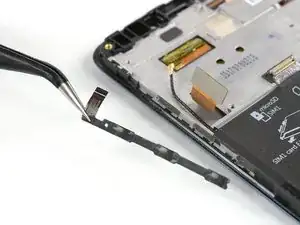
    • Use a pair of tweezers to gently peel the power and volume button unit off the left edge of the phone.

    • Remove the power and volume button unit.

  27. mIwZQoPcWsHfosbh
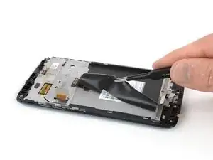
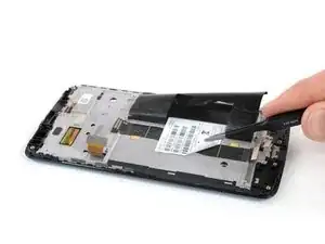
    • Apply the iOpener for about two minutes on the black adhesive tape that covers the antenna and the interconnect cable.

    As mentioned above, the antenna on the US XT1768 is on the opposite side, so I started this step from the opposite side.

    Tom Bartol -

  28. p63EE1HByg6LLsE2
    p63EE1HByg6LLsE2
    LXIeaaPdMCy2dMAq
    GTlKRx2XjarKKadY
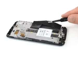
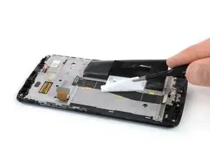
    • Use a pair of tweezers to gently peel the adhesive tape off the antenna and interconnect cable and fold it out of the way.

  29. s3xIrZc3dRi6wFTA
    s3xIrZc3dRi6wFTA
    YkgYXfcSvBVCnOlH
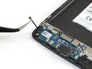
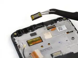
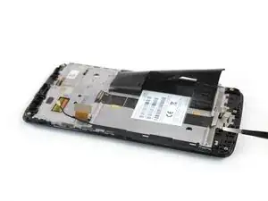
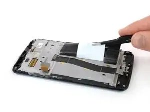
    • Use a pair of tweezers to thread the antenna cable out of its routing.

    • Remove the antenna cable.

  30. RLwgouwYInkHIK5K
    RLwgouwYInkHIK5K
    M5nYamTPByReWL46
    jHY2HRFIxdJPc4gy
    • Use a pair of tweezers to gently peel the product sticker off the interconnect cable.

    • In case you can't remove the sticker or it starts to rip apart you can re-apply an iOpener to loosen the adhesive.

    The plastic sheet in my US XT1768 covers the whole battery compartment and has the sticker attached to the plastic sheet.

    So I removed the plastic sheet with the sticker still attached as one whole unit.

    Tom Bartol -

  31. TAuIi5gXWrTKYObm
    TAuIi5gXWrTKYObm
    muJGWtUtvU5Mq3Ny
    W1ZncKlTtMTPIfgE
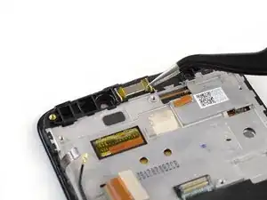
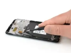
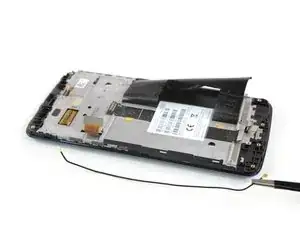
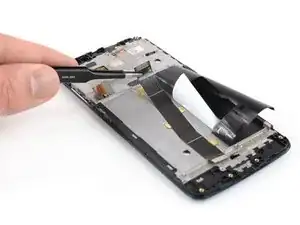
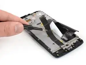
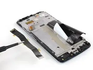
    • Use a pair of tweezers to grab and carefully peel up the interconnect flex cable.

    • Remove the interconnect flex cable.

  32. SkVhkRCyFEyk6S6y
    • Check your replacement part for any other components that might need to be transferred before reassembly.

Conclusion

If possible, turn on your phone and test your repair before installing new adhesive and resealing the phone.

To reassemble your device, follow these instructions in reverse order.

Repair didn’t go as planned? Check out our Answers community for troubleshooting help.

Take your e-waste to an R2 or e-Stewards certified recycler.

Tobias Isakeit

Member since: 31/03/14

107664 Reputation

0 comments