Introduction

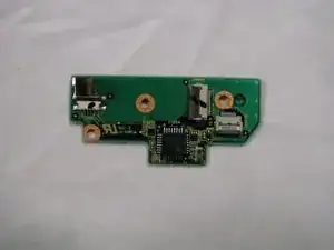
This guide will show you how to gain access to and replace the track pad board in your Panasonic CF-29.

  1. Q1LlhVrXXRipQNLs
    • Locate the bay door for the battery on the left side of the laptop.

  2. h6mfbF2ZDfEn4bdR
    h6mfbF2ZDfEn4bdR
    HLsS2NIP2NZDIW1r
    • Slide the latch to the right and then down to unlock it.

    • Pull out the battery.

  3. X16sPhIIAk1PcWWr
    • Locate the door for the hard drive on the right side of the laptop

  4. WQNQDSKTjrBrqQvB
    WQNQDSKTjrBrqQvB
    tKdIBD2ZNrQFIyFO
    • Push and slide the latch up to open the hard drive door.

    • Pull out the hard drive.

  5. FSQbvcfPXo12LNEW
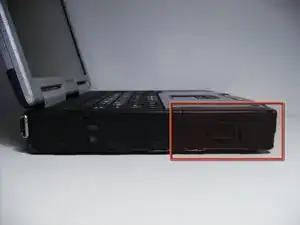
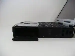
    • Flip the device upside down with the handle facing away from you.

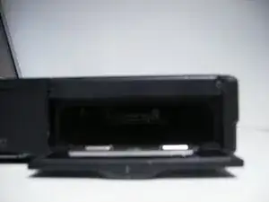
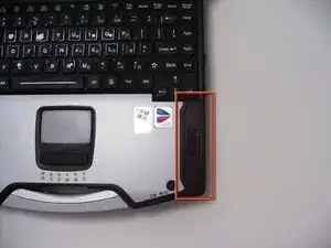
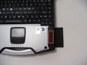
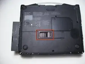
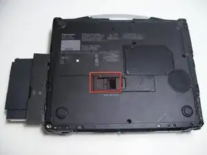
    • Open the optical drive bay by sliding its latch to the right.

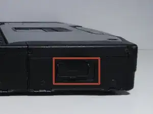
    • Locate optical drive release mechanism on the bottom of the laptop.

  6. igiZjJEo3xfOBr5H
    • Slide the latch cover to the right.

  7. ZA6hifMQSLb1YJVx
    ZA6hifMQSLb1YJVx
    ZyKxqZGFUDbb6uOx
    • Push the exposed switch to the left to eject the optical drive.

  8. LQAoluGSYIBSVyYH
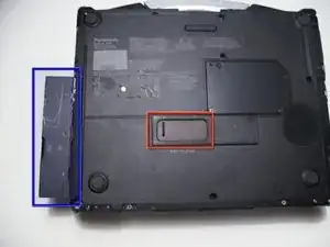
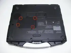
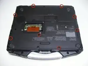
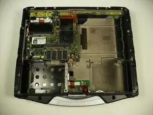
    • Begin by turning the laptop upside down with the handle towards you.

    • Use a Phillips size 0 screwdriver to remove the 4 screws holding down the ram cover.

  9. YNShuNVRHD2kgTMB
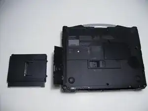
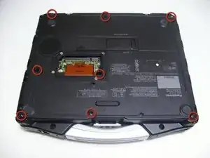
    • Remove the panel and set it aside.

    • Use a Phillips size 0 screwdriver to remove these 8 small screws.

  10. olTmDAePCCWkaBTC
    • Use a Phillips size 1 screwdriver to remove the remaining 8 screws.

  11. PoSREVQ5ThVquIdH
    PoSREVQ5ThVquIdH
    Lbuy1HBVxRyhL2LB
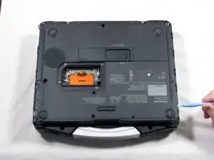
    • Use a plastic opening tool to release, but NOT remove, the back cover because it is sealed with adhesive.

  12. UYMZNkmSyQr5IqNA
    • Be careful when lifting the cover as you may damage some connections.

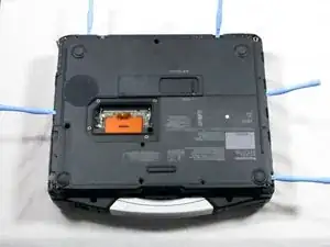
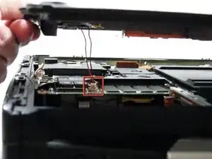
    • Slowly lift the cover so that you can disconnect the red and white wires connecting the speaker to the sound card.

  13. ULLZQiETLcSKPdi3
    • Now the back cover should be off and you can access the inside of the casing.

  14. DH233xfVwDe4eGLw
    • Locate the track pad chip near the handle.

    • Remove the upper right screw.

  15. NMlZsmuAaTLEygxf
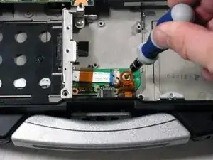
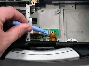
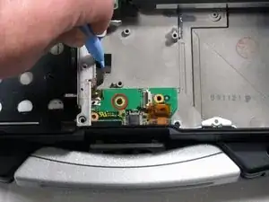
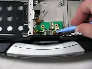
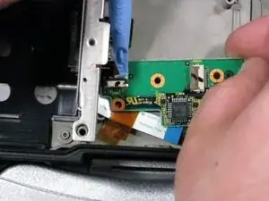
    • Use a pry bar to detach the white ribbon cable shown.

    • Push the brown tab to release the cable

  16. DDUHNLaKyNVbYHS6
    • Remove the screw that was previously concealed under the now removed ribbon cable.

  17. wMPBIUHwpX1hlEg6
    • Remove the rightmost ribbon cable

    • Pry up the brown clip

    • Tug the cable out

  18. QarefhCnQZMEgRYA
    • Pull the track pad slightly up and to the right.

    • Do not completely remove the circuit board because it is still attached.

  19. 4PWjJmxmWQixYvqL
    • Remove the last ribbon cable.

    • Pry up on the brown part to release the ribbon cable.

  20. 2TCLsgpLqooTO3qW
    • You have successfully removed the track pad board.

Conclusion

To reassemble your device, follow these instructions in reverse order.

Dylan Bloom

Member since: 12/04/10

355 Reputation

0 comments