Introduction
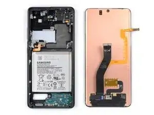
Use this guide to replace a cracked or broken screen on your Samsung Galaxy S21 Ultra.
This guide was performed on the SM-G998B/DS (international) model. Other models have an additional antenna cable sitting in the edge of the midframe.
If the frame is deformed, it's important to replace it to make sure the new screen will mount correctly and won’t suffer damage from uneven pressure.
If your battery is swollen, take appropriate precautions. Before disassembling your device, discharge the battery below 25%. This reduces the risk of a dangerous thermal event if the battery is accidentally damaged during the repair.
Note: This guide instructs you to replace only the screen while leaving the original frame and motherboard in place. However, some replacement screens for this phone come pre-installed in a new frame (a.k.a. chassis), which requires a very different procedure. Make sure you have the correct part before starting this guide.
Although it’s not necessary to remove the interconnect cables to replace the screen we advise doing so. It makes the required motherboard removal and the reassembly way easier.
If you do not replace the adhesive seals when reassembling, your device will function normally, but will most likely lose its water protection.
Before you begin this procedure, be sure to have a set of replacement adhesives for both the rear glass and the screen.
-
-
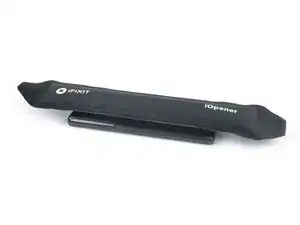
Prepare an iOpener and apply it to the back cover for at least three minutes to loosen the adhesive underneath.
-
-
-
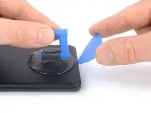
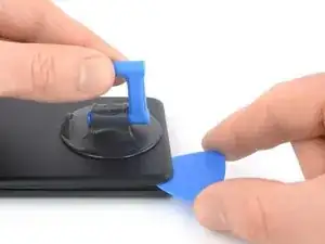
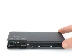
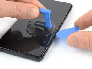
Secure a suction handle to the bottom edge of the back cover, as close to the edge as possible.
-
Lift the back cover with the suction handle to create a small gap between the back cover and the frame.
-
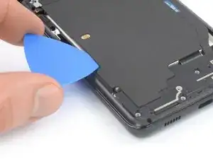
Insert an opening pick into the gap you created.
-
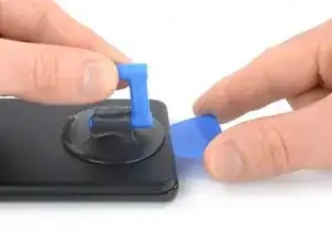
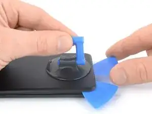
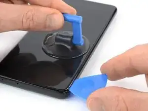
Slide the opening pick to the bottom left corner to slice the adhesive.
-
Leave the opening pick in place to prevent the adhesive from resealing.
-
-
-
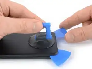
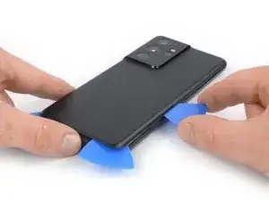
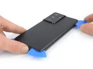
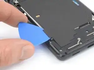
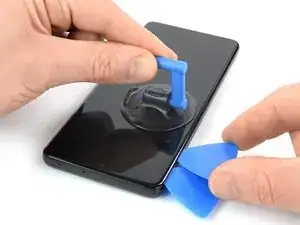
Insert a second opening pick at the bottom edge of your phone.
-
Slide the opening pick to the bottom right corner to slice the adhesive.
-
Leave the opening picks in place to prevent the adhesive from resealing.
-
-
-
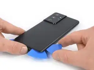
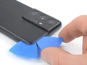
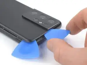
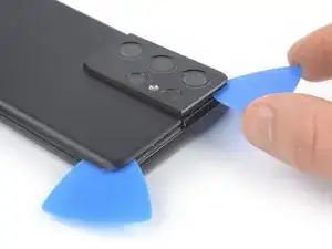
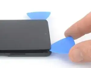
Insert a third opening pick at the bottom right corner of your phone.
-
Slide the opening pick along the right edge of your phone to slice the adhesive.
-
Leave the opening pick in the top right corner to prevent the adhesive from resealing.
-
-
-
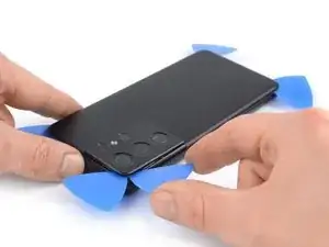
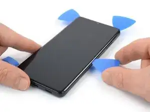
Insert a fourth opening pick underneath the top right corner of your phone.
-
Slide the opening pick along the top edge to slice the adhesive.
-
Leave the opening pick in the top left corner to prevent the adhesive from resealing.
-
-
-
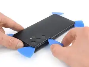
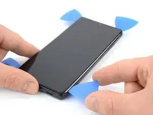
Insert a fifth opening pick underneath the top left corner.
-
Slide the opening pick along the left edge of the back cover to slice the remaining adhesive.
-
-
-
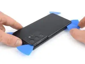
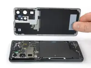
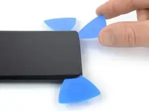
Remove the back cover.
-
This is a good point to power on your phone and test all functions before sealing it up. Be sure to power your phone back down completely before you continue working.
-
Remove any adhesive chunks with a pair of tweezers or your fingers.
-
Use some high concentration (over 90%) isopropyl alcohol to wipe away any adhesive residue.
-
If you're using Samsung custom-cut adhesives, follow this guide.
-
If you're using double-sided tape, follow this guide.
-
-
-
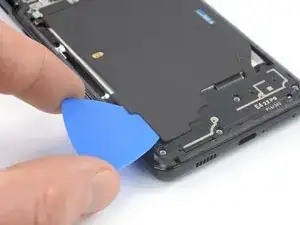
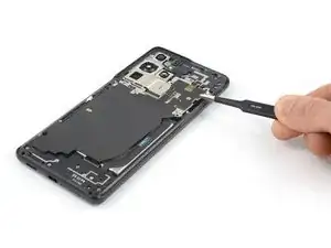
Insert an opening pick underneath the left bottom end of the NFC antenna and charging coil assembly.
-
Carefully slide the opening pick along the bottom left edge of the assembly to separate it from the battery.
-
-
-
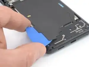
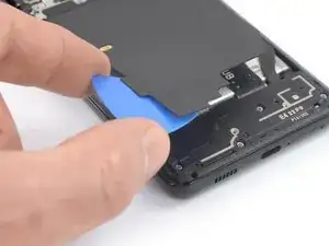
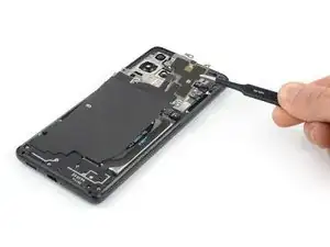
Insert an opening pick underneath the bottom end of the NFC antenna and charging coil assembly.
-
Carefully slide the opening pick along the bottom of the assembly to separate it from the loudspeaker.
-
-
-
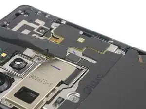
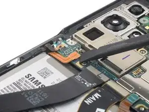
Use a spudger to disconnect the charging coil by prying the connector straight up from its socket.
-
-
-
Use a spudger to disconnect the NFC antenna by prying the connector straight up from its socket.
-
-
-
Use a Phillips screwdriver to remove the five 3.9 mm-long screws securing the NFC antenna and charging coil assembly.
-
-
-
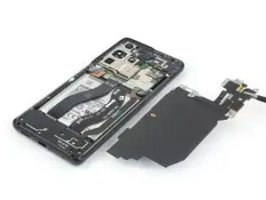
Use a pair of tweezers or your fingers to carefully remove the NFC antenna and charging coil assembly.
-
-
-
Use a spudger to disconnect the battery cable by prying the connector straight up from its socket.
-
-
-
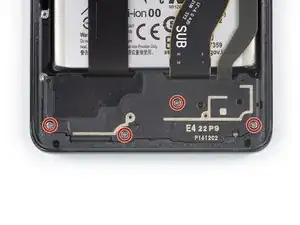
Use a Phillips screwdriver to remove the four 3.9 mm-long screws securing the loudspeaker assembly.
-
-
-
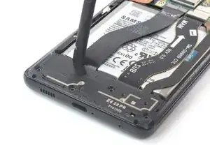
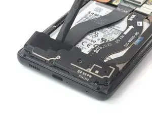
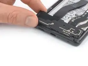
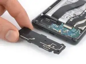
Insert a spudger into the gap between the top edge of the loudspeaker assembly and the midframe.
-
Use your spudger to pry up the loudspeaker assembly by tilting it downwards.
-
-
-
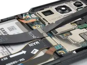
Use a spudger to disconnect the display flex cable by prying the connector straight up from its socket.
-
-
-
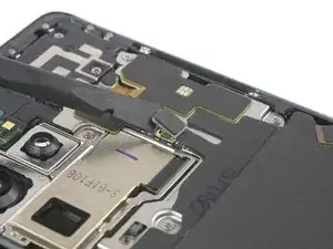
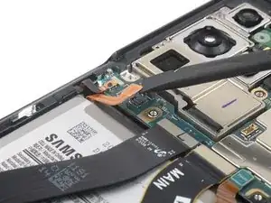
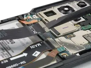
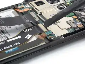
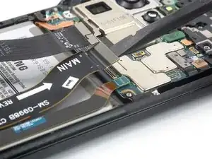
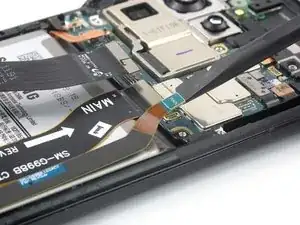
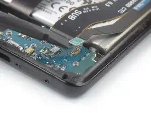
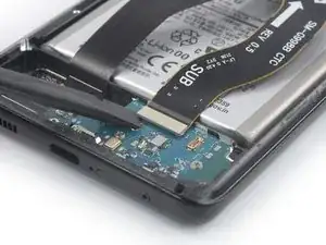
Use a spudger to disconnect the main and interconnect flex cables from the motherboard by prying their upper connectors straight up from their sockets.
-
-
-
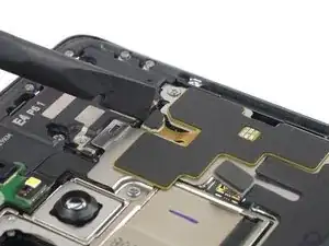
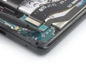
Use a spudger to disconnect the interconnect flex cable from the daughterboard by prying its bottom connector straight up from its socket.
-
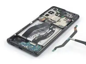
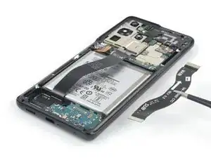
Use your fingers or a pair of tweezers to carefully remove the interconnect flex cable.
-
-
-
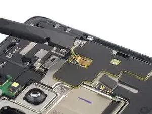
Use a spudger to disconnect the main flex cable from the daughterboard by prying its bottom connector straight up from its socket.
-
Use your fingers or a pair of tweezers to carefully remove the main flex cable.
-
-
-
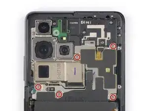
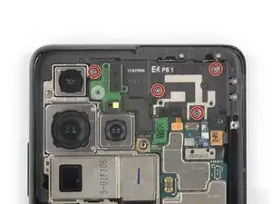
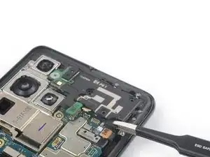
Use a Phillips screwdriver to remove the four 3.9 mm-long screws securing the earpiece speaker and laser AF module assembly.
-
-
-
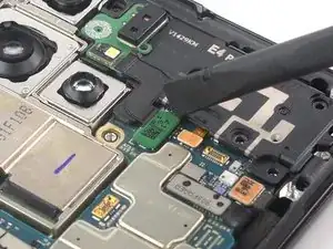
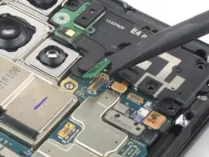
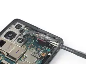
Use a spudger to disconnect the laser AF module and earpiece speaker flex cables by prying the connectors straight up from their socket.
-
-
-
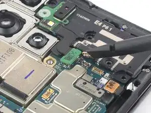
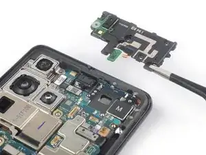
Grab the bottom right corner of the earpiece speaker and laser AF module assembly with a pair of blunt nose tweezers and carefully lift it upwards.
-
Remove the earpiece speaker and laser AF module assembly.
-
-
-
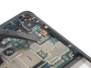
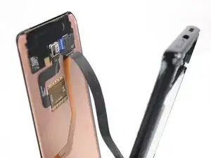
Use a spudger to disconnect the in-display fingerprint and antenna flex cables by prying the connectors straight up from their socket.
-
Carefully bend both connectors to the side to free the motherboard.
-
-
-
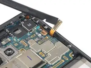
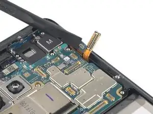
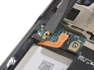
Use a spudger to disconnect the front facing camera cable by prying the connector straight up from its socket.
-
-
-
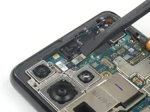
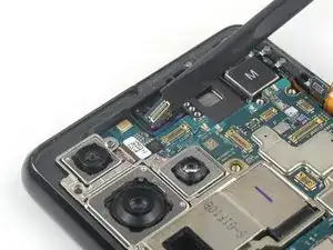
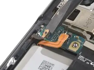
Use a spudger to disconnect the power button flex cable by prying the connector straight up from its socket.
-
Carefully bend the connector to the side to free the motherboard.
-
-
-
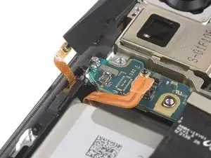
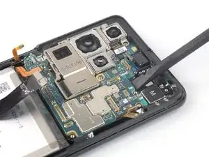
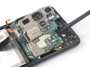
Insert an spudger underneath the top edge of the motherboard next to the vibration motor.
-
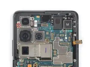
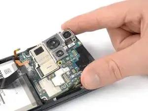
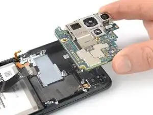
Use your spudger to pry up the motherboard by tilting it downwards and twisting it to the side at the same time.
-
-
-
Apply a heated iOpener to the screen to loosen the adhesive underneath. Apply the iOpener for at least 5 minutes.
-
-
-
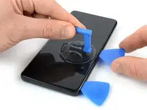
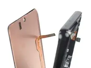
Once the screen is warm to touch, apply a suction handle to the left edge of the screen and as close to the edge as possible.
-
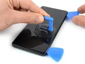
Lift the screen with the suction handle to create a small gap between the screen and the frame.
-
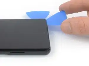
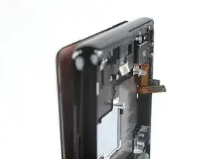
Insert an opening pick into the gap between the midframe and the screen.
-
Slide the opening pick to the top left corner of the screen to slice its adhesive.
-
Leave the opening pick in place to prevent the adhesive from resealing.
-
-
-
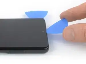
Insert a second opening pick at the top left corner and slide it to the bottom left corner of the screen to slice the adhesive.
-
Leave the opening pick in place to prevent the adhesive from resealing.
-
-
-
Insert a third opening pick at the top left corner of the screen.
-
Slide the opening pick along the top edge of the phone to slice the adhesive.
-
Leave the opening pick in place to prevent the adhesive from resealing.
-
-
-
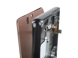
Insert a fourth opening pick underneath the top right corner of the screen.
-
Slide the opening pick along the right edge of the screen to slice the adhesive.
-
Leave the opening pick in place to prevent the adhesive from resealing.
-
-
-
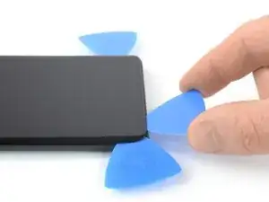
Insert a fifth opening pick at the bottom right corner of the screen.
-
Slide the opening pick along the bottom edge to slice the remaining adhesive.
-


If possible, turn on your device and test your repair before installing new adhesive and resealing.
To reassemble your device, follow these instructions in reverse order.
After you've completed the repair, follow this guide to test your repair.
The best way to secure the new screen is to apply a sheet of custom-cut double-sided tape to the back of the screen.
Take your e-waste to an R2 or e-Stewards certified recycler.
Repair didn’t go as planned? Try some basic troubleshooting, or ask our Answers community for help.