Introduction
Use this guide to replace the USB-C port and charging board in your Samsung Galaxy S22+.
Before you begin, refer to the Samsung Self-Repair document for safety information.
Note: Retaining water resistance after the repair will depend on how well you reapply the adhesive, but your device will lose its IP (Ingress Protection) rating.
-
-
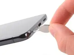
Insert a SIM eject tool, bit, or straightened paper clip into the SIM card tray hole on the bottom edge of the phone.
-
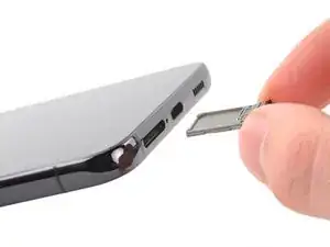
Press the SIM eject tool into the SIM card tray hole to eject the SIM card tray.
-
Remove the SIM card tray.
-
-
-
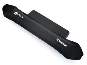
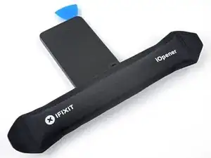
Prepare an iOpener and apply it to the bottom edge of the back cover for three minutes to loosen the adhesive underneath.
-
-
-
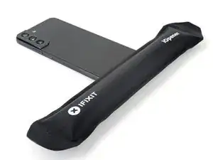
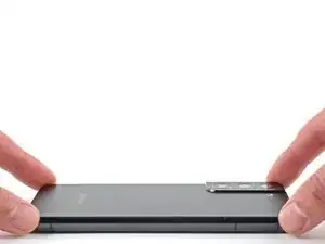
Secure a suction handle to the bottom edge of the back cover, as close to the edge as possible.
-
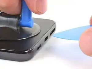
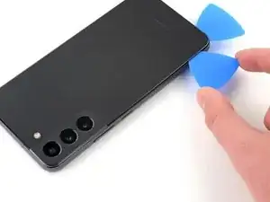
Lift the back cover with the suction handle to create a small gap between the back cover and the frame.
-
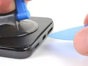
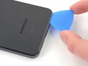
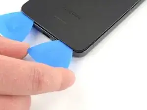
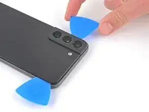
Insert an opening pick into the gap you created.
-
-
-
Remove the suction handle.
-
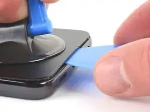
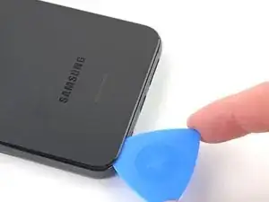
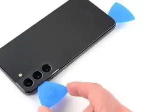
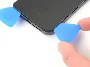
Slide the opening pick along the bottom edge to slice the adhesive.
-
Leave the opening pick inserted near the bottom left corner to prevent the adhesive from resealing.
-
-
-
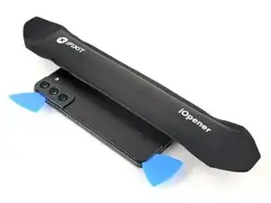
Apply the heated iOpener to the left edge of the phone for 3 minutes to soften the adhesive.
-
Reheat your iOpener for 30 seconds if necessary.
-
-
-
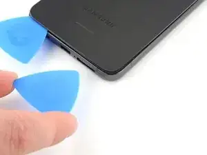
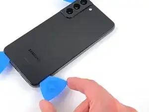
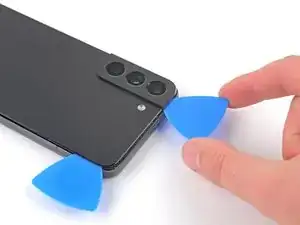
Insert a second opening pick into the gap created near the bottom left corner.
-
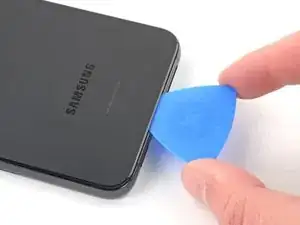
Slide the opening pick along the left edge to slice the adhesive.
-
Leave the opening pick inserted near the top left corner to prevent the adhesive from resealing.
-
-
-
Apply your heated iOpener to the right edge of the phone for 3 minutes to soften the adhesive.
-
Reheat your iOpener for 30 seconds if necessary.
-
-
-
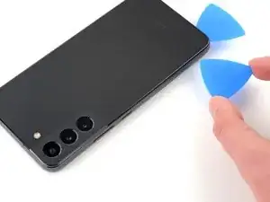
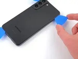
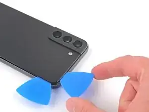
Insert a third opening pick into the gap created along the bottom edge.
-
Slide the opening pick around the bottom right corner of the back cover to slice the adhesive.
-
-
-
Continue sliding the opening pick up along the right edge of the back cover to slice the adhesive.
-
Leave the opening pick inserted near the top right corner to prevent the adhesive from resealing.
-
-
-
Apply your heated iOpener to the top edge of the phone for 3 minutes to soften the adhesive.
-
Reheat your iOpener for 30 seconds if necessary.
-
-
-
Slide the opening pick in the top left corner across the top edge to separate the remaining adhesive.
-
-
-
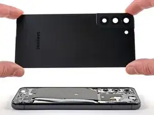
Remove the back cover.
-
This is a good point to power on your phone and test all functions before sealing it up. Be sure to power your phone back down completely before you continue working.
-
Remove any adhesive chunks with a pair of tweezers or your fingers. Apply heat if you're having trouble separating the adhesive.
-
If you're using Samsung custom-cut adhesives, follow this guide.
-
If you're using double-sided tape, follow this guide.
-
-
-
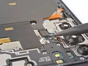
Use the pointed end of your spudger to pry up and disconnect the charging coil's press connector from the motherboard.
-
-
-
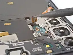
Use the pointed end of your spudger to pry up and disconnect the NFC antenna cable from the motherboard.
-
-
-
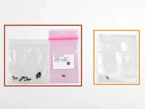
If you're using the Samsung Self Repair Kit, take a moment to identify your screws and label them accordingly:
-
Label the bag with the most screws and the colored bag #3428.
-
Label the clear bag with two screws #3229.
-
-
-
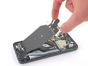
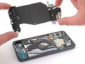
Insert your spudger in between the left edge of the loudspeaker and the frame.
-
Pry up to disconnect the clips securing the loudspeaker.
-
-
-
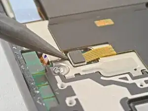
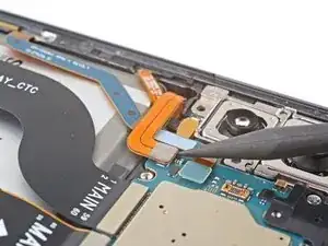
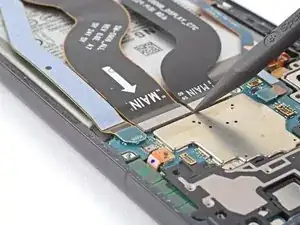
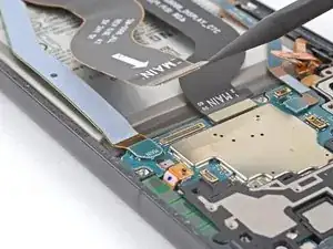
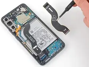
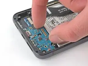
Use your spudger to pry up and disconnect the primary interconnect cable from the motherboard.
-
Use your spudger to pry up and disconnect the secondary interconnect cable from the motherboard.
-
-
-
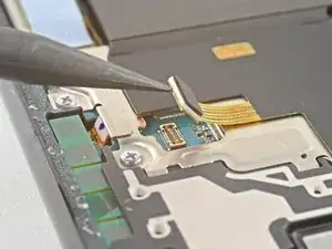
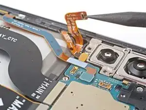
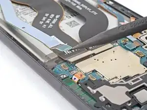
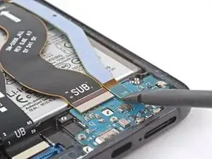
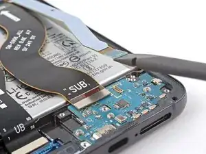
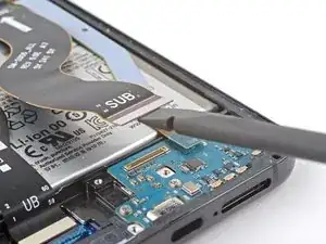
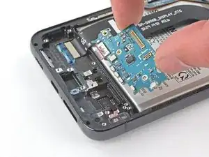
Use your spudger to pry up and disconnect the primary interconnect cable from the charging board.
-
Use your spudger to pry up and disconnect the secondary interconnect cable from the charging board.
-
-
-
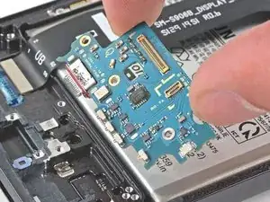
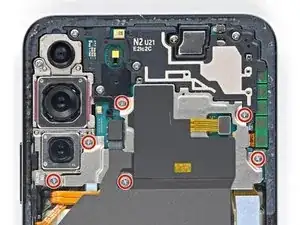
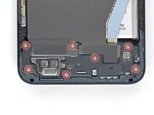
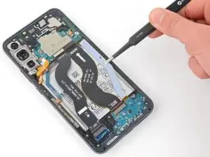
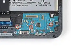
Use your Phillips screwdriver to remove the three 3.4 mm screws securing the charging board.
-
-
-
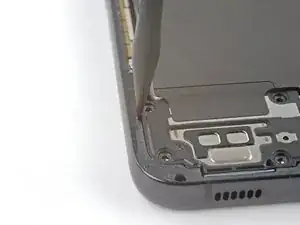
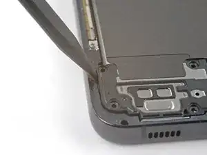
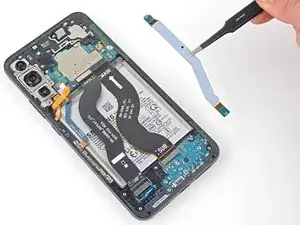
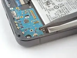
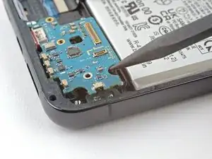
Insert the pointed end of a spudger between the top right edge of the charging board and the frame.
-
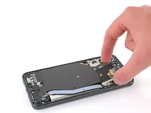
Pry up to lift the charging board enough to reach it with your fingers.
-

To reassemble your device, follow the instructions in reverse order and perform the opposite actions, e.g., "reattach" instead of "removing." Skip steps that use heating and prying, and pay close attention to the 📌 bullets as you work through the steps.
After you've completed the repair, download the Samsung Members App from the Galaxy Store or the Play Store, and Samsung Self-Repair document (beginning page 10) to make sure your device is fully functional.
Take your e-waste to an R2 or e-Stewards certified recycler.
Repair didn’t go as planned? Try some basic troubleshooting, or ask our Answers community for help.