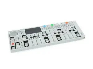
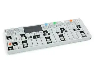
Introduction

The UI board is responsible for the knobs and keyboard action and connects to the speaker. If it fails there will be no fun at all.

This guide will show you how to replace the UI board of your OP-1.

  1. vxoTLiJxFDPOji5X
    vxoTLiJxFDPOji5X
    ajlj12AYLBNXKv6o
    MSgrKiNeLFhWdEpd
    • To get to the screws beneath the keyboard you need to take some keys off. You can use either an opening tool or an opening pick. The first picture shows how it should look like with all the necessary keys off (12 in total).

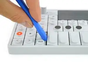
    • The four longer keys from the fingerboard are to be handled from the left side to get them off.

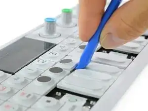
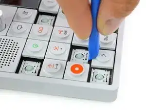
    • The eight smaller keys need to be levered from the bottom up.

  2. NKEIk4cFqiaAPIDr
    NKEIk4cFqiaAPIDr
    faMO21YfJAINC3yK
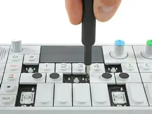
    • The scissor mechanism of the eight small keys are obstructing the underlying screws.

    • By using again an opening tool or opening pick these can be snapped off easily.

    • When reassembling be sure to place them in with the correct side facing upwards.

  3. SLEyuvdxWjnDuCUg
    SLEyuvdxWjnDuCUg
    RCYV1CYSlXFdOVKE
    MpduwLQ5mTtWh4lM
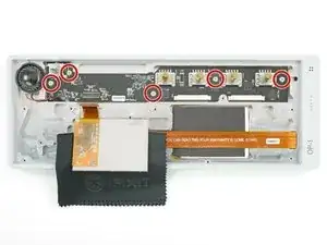
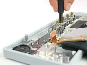
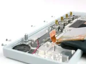
    • Loosen those 12 screws with a Phillips #00 screwdriver.

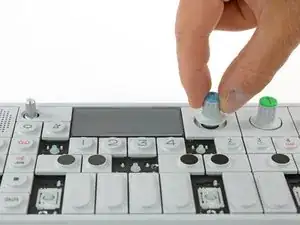
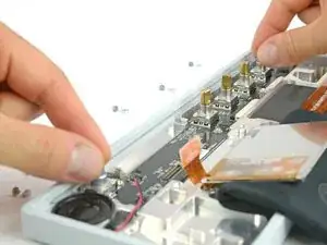
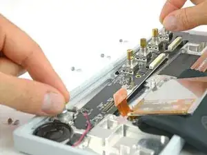
    • Then just pull off the four rotary knobs and the volume knob.

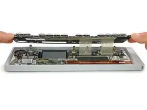
    • Now it is possible to slightly lift the keyboard and set it back.

    Your missing the ribbon decoupling step, unless you skipped it because it’s such a tight squeeze to get back in.

    William “Zoe” FitzGerald -

    The concept of removing the square panels that the knobs sit on was skipped.

    Station 2Station -

  4. 51sGIqr3XDf63GZr
    51sGIqr3XDf63GZr
    TtJMQEP5jZOmWNRo
    1qoL6TEjDLJueeCK
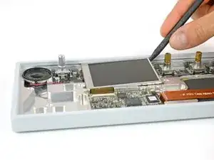
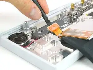
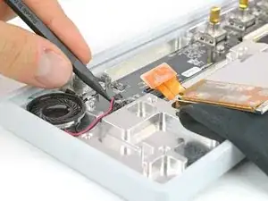
    • The display is held in place with a mild adhesive. A spudger helps you to get it free.

    • Be careful since the flex cable is still connected.

    • Make sure the display won't be damaged when you flip it over to the front to access the UI board.

  5. tcMhViloAUgklmwJ
    tcMhViloAUgklmwJ
    cmYNrUQdVrsJlDmT
    • Unplug the DSP flex cable from the UI board.

    • Unplug the speaker cable from the UI board.

  6. fvNCGBRLMDGkuxeD
    fvNCGBRLMDGkuxeD
    Sa4B5xsiuZ135SjY
    LyMWdsIJsHCNLeYX
    • Use a Phillips #00 screwdriver to remove the five screws on the UI board.

    • To each screw there is a thick washer to fix the board. Don't loose them.

  7. 1ZdH1VPGovT3Thte
    1ZdH1VPGovT3Thte
    JT2i6MQbwk1P2byn
    JldP2KScVkrZJrBu
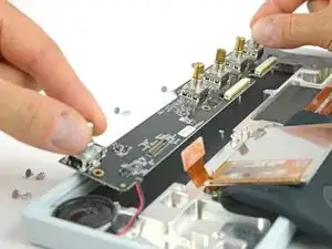
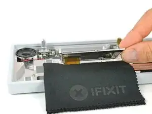
    • Now the UI board is free to take out. You can grab it by the knobs and start lifting it on the right side half way out.

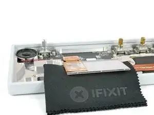
    • On the left side the speaker and its cable might be in the way to get it out straight. Just move it diagonally to the right to get it out completely.

    • Make sure the black plastic mat underneath the UI board stays inside.

    • After reassembling you want to check the board with the internal test function. You can enter it by holding the "COM" button while powering on, then choose the function test (0).

    Thanks a ton this helped so much!

    William “Zoe” FitzGerald -

Conclusion

To reassemble your device, follow these instructions in reverse order.

Tobias Isakeit

Member since: 31/03/14

107643 Reputation

One comment

Can anyone recommend a good adhesive tape to fix the screen in place after doing the repair?

ossian moncreiffe -