Introduction
-
-
First check, if this fix applies to you: Remove the vacuum bin and listen if the clicking noise has vanished. If so, this fix will help you
-
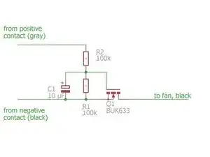
The source of the clicking noise are voltage spikes (1-2 milliseconds duration) which are sent to the vacuum bin motor, giving it a short, hearable kick. We will add a soft-start functionality to the vacuum bin motor such that those spikes will have no effect.
-
-
-
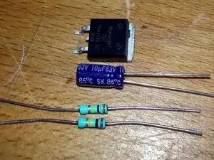
Parts you need:
-
one n-FET (I used BUK663) but any n-FET with a voltage rating > 20V , a current rating >10A and a gate-source threshold voltage Vgs<5V should work
-
Two 100kOhm resistors
-
one 10 µF/25V capacitor (careful, has positive and negative side!)
-
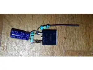
Solder everything together according to the schematic
-
-
-
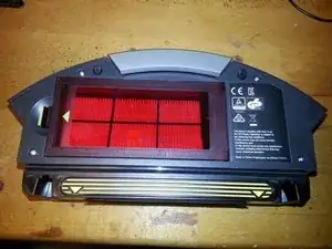
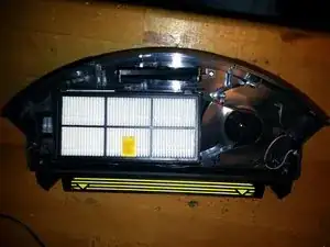
Open the lid of the vacuum bin by removing the four silver screws and carefully remove the lid
-
-
-
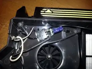
Cut the black wire and insert the circuit. Do not forget some large shrinking tube to cover the whole circuit later (not pictured)
-
Add a wire between the gray-wired connection tab and the resistor R2 (white wire in the picture). Add some shrinking tube to the resistor to prevent short-circuits.
-
WARNING: Do not solder the wires when the connection tabs are in the plastic holder - the plastic will melt. Remove the contacts from the plastic before soldering
-
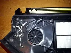
Shrink tube over the whole circuit.
-
-
-
You can test the circuit with a 12V or 9V battery/voltage supply. Positive voltage is the grey-cabled tab, negative the black-cabled one. The motor should start with a short delay (1s or so)
-
Reassemble vacuum bin and enjoy the silence.
-

To reassemble your device, follow these instructions in reverse order.
12 comments
This 100% correctly identified my issue with continuous clicking coming from the filter fan. I will add that this happened on my unit even when it was removed from the charger and powered off. However the soft start circuit you created did not work for me. This may be due to incorrect wiring or using the wrong components, but I believe I followed both to the best of my ability. The mosfet I used is the STU13N65M2 n-channel MOSFET (which I believe matches the minimal specs you provided.) Panasonic 10uF 50v caps, and nice 1W 100K ohm resistors. No dice…
I just checked the specs of that MOSFET, and it differed from the website where I bought it. The Vgs is ~25 volts, so that’s probably where I went wrong. I will update with a working part number if I can find one.
After further experimentation I discovered I was not correctly identifying the MOSFET pinout and it was miswired. By looking at your physical example I was able to see what I was doing wrong. Maybe add a clearer indication of the MOSFET’s pinout on the schematic if you have a chance.