Introduction

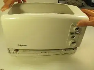
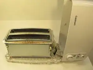
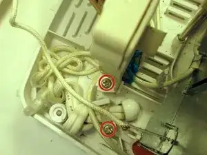
This guide is part of a reverse engineering project for EE 460. We were given a Cuisinart 4-Slice Tandem Toaster, and we broke it down into its most basic components.

  1. pV1HZvSS6scUat5N
    • This Cuisinart Toaster's technical highlights include:

    • Tandem, 2-slot toaster

    • 1½" wide toasting slots

    • Function control dial

    • Bagel, Defrost and Reheat selections

    • Blue LED shade control with large, easy-to-read numbers

    • 2 or 4 slice button; cancel button

    Is there a simple fix when the toast won’t stay down.? The handle just keeps popping up.

    mannyvalder@gmail.com -

  2. xSrNlgPASbdDFksC
    xSrNlgPASbdDFksC
    6MOeKBt2UqghiXYf
    • Unplug the toaster prior to teardown.

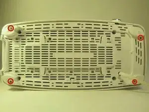
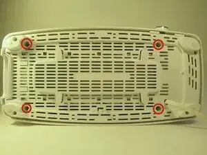
    • On the bottom of the toaster, unscrew the 4 Torx screws (using a screw driver)

    5/2021 - by coolblueglow - Some models will have Phillips head screws in these locations. A #2 Phillips will get them out o.k.

    K Lynch -

    …and the fasteners shown in these photos are not “torx”. they are Phillips. Further, note that you will need a regular #2 and a #1 stubby to get the controls off as shown in step 7. A regular #2 will not fit in the top screw well, and a regular length Phillips will not allow you to get a straight shot onto the screw head.

    K Lynch -

  3. NkOEJKQnvdGGqFWL
    NkOEJKQnvdGGqFWL
    QWvvcdgyEXAKQylf
    QJnVxQYyWGCR6Drp
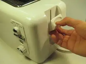
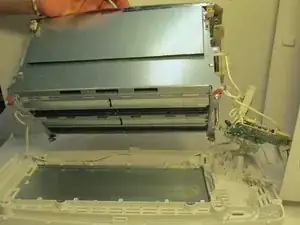
    • Pull the press handle down and away from the toaster to disconnect the body.

    • Lift up the body of the toaster.

    Note that on the underside of the lever that the handle is connected to, towards the inside, you need to release a plastic hook tab to remove the lever.

    Owen Gallagher -

  4. SXypZb5tVrGZWKMe
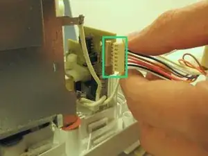
    • Pull the pin header cable to disconnect the body of the toaster from the main assembly unit.

  5. QKEGIxZaaZJN5LTc
    QKEGIxZaaZJN5LTc
    cNnCq4mPOyqIsVtI
    BL4QmNxVTAxrkMP6
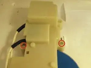
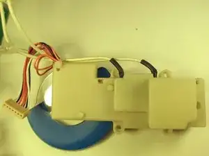
    • Remove the 5 Torx screws to detach the heating unit from the bottom of the toaster unit.

    Note that the part identified in this description as the “heating unit” is NOT the heating unit. Rather, it is the primary current control switch. This is a MECHANICAL switch which conducts the heavy current required to heat the heating elements, which are located inside the toaster bays. The heating elements are the flat metallic ribbons that you see glowing dull orange when the toaster is operating. When you push down the toaster handle, that action physically closes these contacts, which then conduct current to the heating elements. When you push the right-hand switch on the front called “2 slices / 4 slices” that is a SECOND and fully mechanical switch which interrupts current to just one of the four heating elements, thereby disabling 1/2 of the second toaster bay. (The center section is a single winding, and always heats on both sides) So, to be clear - ALL current switching in this toaster is performed by mechanical switches. The electronics described later only manage toast-time functions.

    K Lynch -

  6. xiabEPvZpyTS5wnj
    xiabEPvZpyTS5wnj
    FPNPnG24VFdEABvJ
    eMJ54TKIP4emx5f1
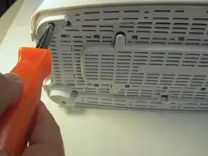
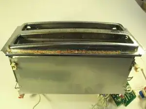
    • Using a plastic opening tool, carefully pry open the metal casing underneath the toaster.

    The four sheet metal twist-lok retaining tabs (with the orange paper washers stuck on them, as seen in the picture) are simply metal tabs. They are twisted into place to retain the toaster body onto the plastic baseplate. You will need small pair of needlenose pliers, a flat screwdriver and perhaps a pair of heavy hemostats to be able to straighten them out enough to line them up with the factory slots in the plastic base. A “plastic tool” will not work for this function, and if you force it without untwisting them, you will break the plastic baseplate.

    K Lynch -

  7. PBFresCkbuDuXTyE
    PBFresCkbuDuXTyE
    f2KHVlCv2QBZHgPK
    Ia5MmnRYAlegTSSy
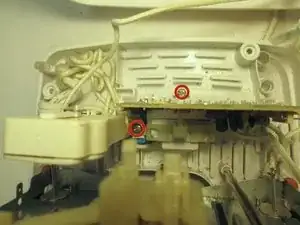
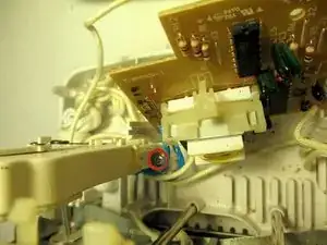
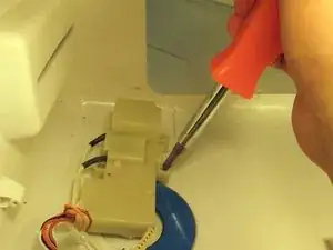
    • Remove the screws to detach controls from the plastic shell of the toaster.

    Note that when you reinstall this part, you will need to properly phase up the rotary control face for the browning selector knob, as well as the four click rotary selector for Toast/Bagel/etc. If you do not phase them up correctly, the switches will not align with the housing, or will be blocked from their full range of travel. Don’t miss this detail. Check rotary switch and browning level adjustment knob for full range of travel BEFORE reassembling the toaster.

    K Lynch -

    Also, note that you will need a #2 and a #1 stubby Phillips to get the controls off as shown in step 7. Notice how that big orange screwdriver they’re showing in the picture is being held at an extreme angle? Why? Simple - because the tool is TOO LONG. :-) The handle is hitting the other side of the body of the toaster. You will never get these three screws out with this tool. You MUST have a short or stubby #2 or #1 (or a tapered shaft #2 bit in a stubby handle, ratchet handle, etc.) And yes, you WILL need to deal with this tapered issue, because a regular sized #2 Phillips stubby driver shaft will not fit in the top screw’s recessed well, even though the screw heads are actually #2 Phillips. That’s a manufacturering duh right there.

    K Lynch -

  8. BWZaugTsNkepcpJk
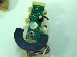
    • Interior of the user control interface

  9. RN2hhXMfgEqyqTMC
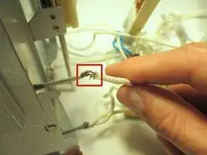
    • Remove the soldered wire that is hooked to each part of the end plate assembly.

    I would NOT “remove the soldered wire”. First of all, it is not “soldered” - it is crimped in place and there is no real reason to remove it for most service procedures. Second, note that the MOST COMMON FAILURE for this toaster is the failure of the center heating element power connection. Follow the cloth covered high temperature wire that passes into the bottom of the center element on the right side of the toaster chamber. It will lead you to where this failure occurs. This connection is only crimped, and highly prone to corrosion. When it corrodes, the center element will not heat, or will heat poorly or intermittently. The solution is to disassemble the toaster chamber enough to access this difficult to get to piece. Restrip the wire, open up the crimped rivet end, clean it, and then recrimp and solder using only SILVER braze. Do NOT use lead solder for reasons of toxicity. Do not use silver solder either, as the toaster element gets hot enough to melt solder. If you don’t have braze, crimp and hope.

    K Lynch -

  10. YdN32lPWELB6f1US
    YdN32lPWELB6f1US
    whKdYjHNmiPwIxn6
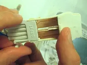
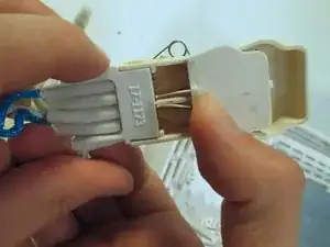
    • Heating Unit

    Again, this is NOT a “heating element”. This is a mechanical switch controlling current to the heating elements, which are located inside the toaster chamber. Yeah…the glowing orange things that make the toast. THOSE are the “heating elements”.

    K Lynch -

  11. cSn1eBIaTe1TqBsp
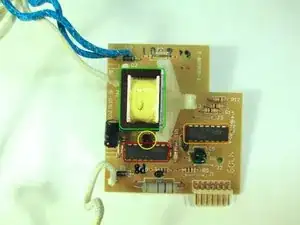
    • This is the Circuit Board used for controlling each subsystem of the toaster.

    • The integrated circuit marked 4541 contains an oscillator which oscillates at some hundreds or thousands of oscillations per second, the speed being determined by the browning setting. It also contains a binary counter which can count up to 65,536.

    • The integrated circuit marked 4066 contains several logic gates which select the count value required for normal, defrost or reheat.

    • During the count, the logic gates supply a small current to the transistor, causing it to energise the electromagnet. At the end of the selected count, the logic gates switch this current off and the transistor de-energises the electromagnet.

    • While energised, the electromagnet holds the lever down. When the current is switched off the lever is released and the spring pops the toast up.

    • Toasters of this age frequently use these "4000-series" integrated circuits as they can run off a wide range of supply voltages. Newer toasters use a microcontroller (essentially a simple micro computer) as this is more flexible in its functions and can also easily drive LEDs to show you what the toaster is doing.

    A great description of the timer circuit in this unit! Very helpful - and it illustrates the point well that this toaster uses ONLY time manipulation to adjust brownness. The temperature of the toast elements is absolutely fixed. They are “on” or “off”, period.

    K Lynch -

  12. xebFQCB5ZkWE5Zxk
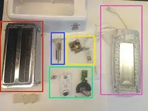
    • Main Assembly Unit

  13. RpiUg6qHpLImZAW6
    • Main Element Assembly

    • Crumb Tray with Power Cord

    • Circuitry with Heating Component

    • User Control Interface with Buttons

    • Press Handle Spring

    If your problem is the center element is not glowing, but the outside elements in both toasting chambers is glowing - then go right to step 9 and read my comment. This will help you to decide whether this repair is within your skills. If you are mechanically adept and have a few hand tools, it is easy to fix. Reading my comment will merely tell you right where to look for the problem, saving you diagnosis time.

    K Lynch -

Lucas Tintikakis

Member since: 03/03/14

133 Reputation

3 comments

Have this broken device and would be glad to us this demonstration to fix it!

Robert Scherer -

Thanks for this great post-up. Saved me a lot of time not having to figure out the disassembly. Hope my comments will further help others trying to do the same.

Cheers!

Keith

K Lynch -

Muy detallado desmontaje felicitaciones

Carlos López (Spain - España) -