Introduction
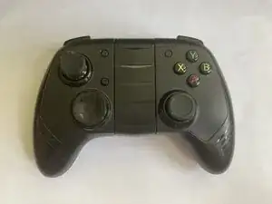
- Released alongside the 2014 iPhone 6, this made for iPhone certified (MFI) controller was designed to be compatible with iOS devices.
- Today, Apple™ devices are compatible with modern PlayStation and Xbox controllers.
- This teardown is meant to see how the Moga Rebel Controller was designed and built.
-
-
Lift the phone mount from the bottom. It swivels on a hinge at the top of the controller.
-
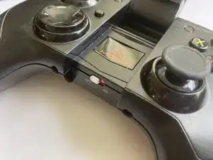
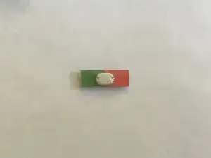
Turn the switch to the left "OFF" position, so that red is showing.
-
-
-
Make sure the phone mounting arm is up, and then separate the back cover along the visible seem.
-
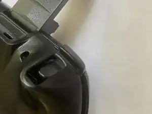
The triggers (L2 and R2) can be pushed in to help lift the back case.
-
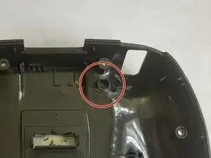
No cables or other internal parts are attached to the back, but the reset button may fall out when lifting it.
-
The third image and red circle show where the reset button goes from the inside of the controller.
-
-
-
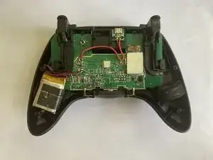
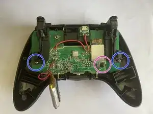
Reparability flaws are now visible:
-
The micro USB daughter board is separate from the main board, which would be otherwise good, except that it is melted in with plastic, and the wires are soldered on.
-
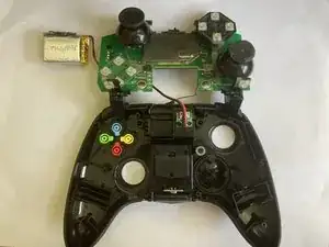
Like the micro USB port, the small (3.7V, 680mAh, 2.52 Wh) battery is soldered on to the main board. By design, replacing the battery needs a soldering iron.
-
Setting flaws aside, a weight can be seen in the controller. It is on the right side of the controller pictured, and the left side when held. It can be lifted out without tools. The added weight is 25 grams, contributing 12.8% of the controllers weight (195g).
-
-
-
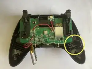
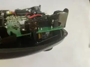
Lift the battery, which covers the left screw.
-
Use the JIS0 (Philips) bit. Unscrew the black screw, which is circled in pink. Next, unscrew the two identical silver screws, circled in blue. Unscrew the black screw, which is circled in pink.
-
The silver screws secures the trigger components and main board to the top case. The black screw secures the main board to the D-pad board.
-
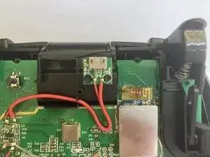
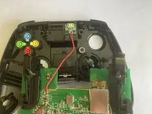
There is a small black wire antenna for bluetooth. It is taped on to the plastic case to the left of the micro USB port. use a spudger to lift the tape.
-
-
-
Take the board out of the case by lifting it up (keeping it as level as possible), and then down.
-
Fold the main board over above the case.
-
the A B X Y and D-pad buttons are connected without being soldered. repairs are still complicated by the adhesive used to keep them in place. Additionally, the D-pad shares the cable with the L1 shoulder button, and the A B X Y shares with the R1 shoulder button.
-
-
-
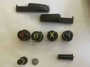
The L1 and R1 buttons can be removed. They can be removed without lifting the main board.
-
The A B X Y buttons can be removed, along with the pause, bluetooth pairing mode, and battery button. The battery button is not pictured. The pause button is in the bottom left of the first photo, and uses a rubber pad.
-
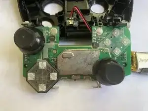
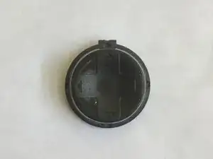
The D-pad can be lifted out, and the power switch can be too.
-
-
-
The joystick cover is glued to the joystick switch, making cosmetic replacements virtually impossible .
-
The joystick switch is soldered onto the main board, making replacing them for drift very difficult, or impossible.
-