Einleitung

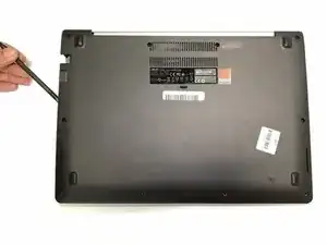
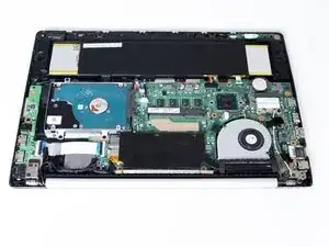
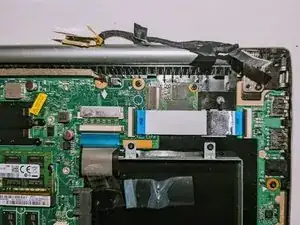
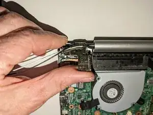
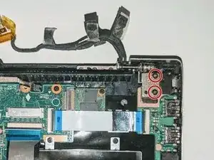
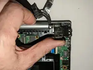
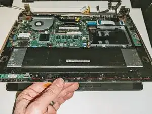
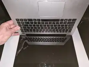
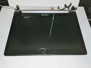
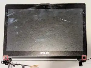
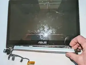
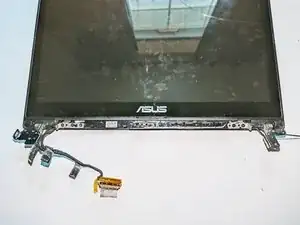
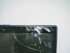
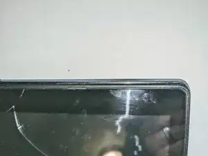
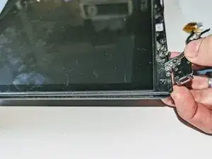
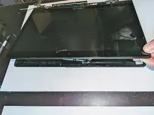
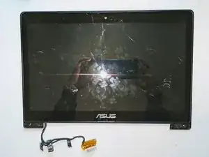
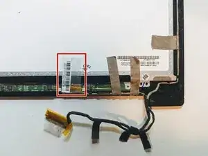
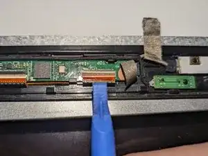
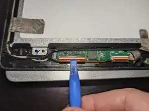
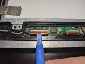
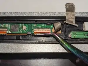
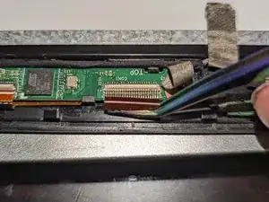
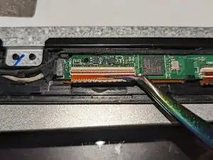
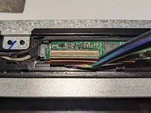
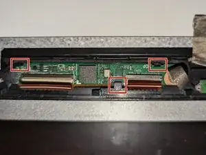
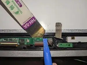
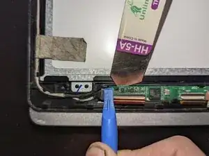
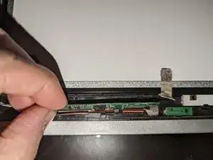
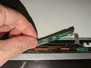
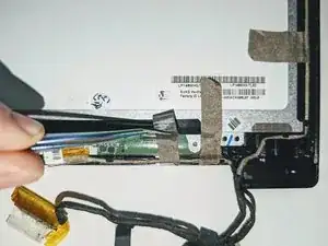
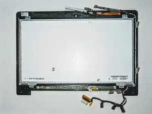
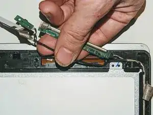
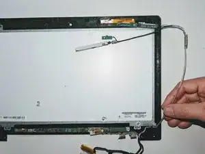
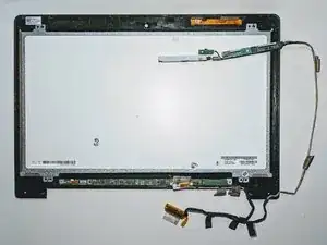
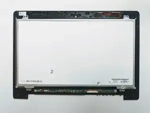
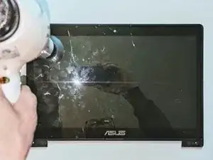
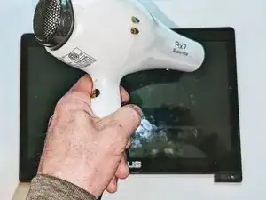
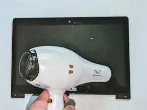
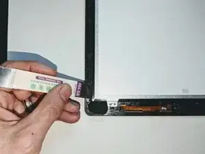
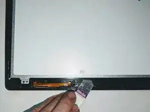
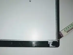
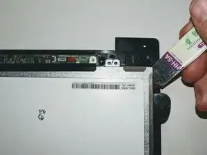
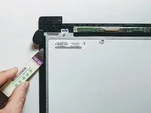
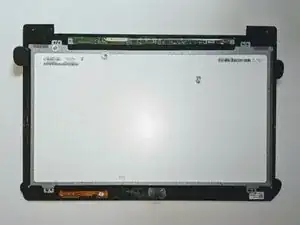
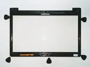
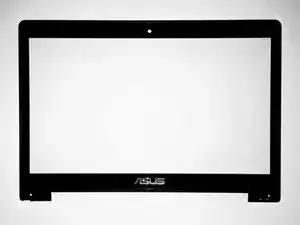
If your ASUS VivoBook S400C has a broken touchscreen or continues to have issues even after going through the touch screen trouble shooting guide to rule out any software issues, use this guide to replace it. Before you begin, make sure the laptop is completely turned off and the battery has been removed.

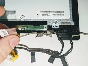
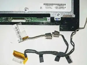
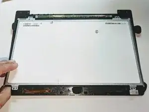
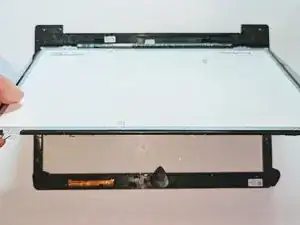
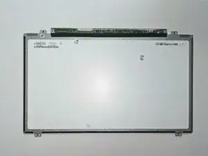
The digitizer is not bonded to the LCD display, and so can be replaced without having to also replace the LCD if the LCD is not damaged. Although the digitizer is available without the front bezel, this guide does not address separating the touch screen from the bezel but only shows how to replace the assembly as a single unit.

Warning: If the glass display is completely shattered, please remain safe by following the directions here on how to tape over any glass and prevent being hurt.

If there is a possibility you will need to replace the LCD adhesive and want to have all parts on hand before you begin, read through the ASUS VivoBook S400C LCD Adhesive Replacement guide and consider ordering the 3 mm Double Sided Adhesive Tape.

  1. HkGAAb6CZRqXFLPE
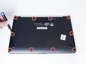
    • Flip the device over and remove the ten 5.7 mm screws with a Phillips #0 screwdriver.

  2. rgGvNFvEhEGnfJ4u
    rgGvNFvEhEGnfJ4u
    axgx2HguWeMp3yjC
    • Use a spudger or your fingers to go around and lift the edges and release the back panel.

  3. 3KTeWNBFWIWWKbTa
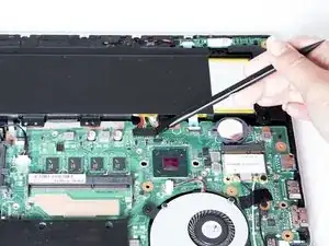
    • Using a spudger, lift up the plug connecting the battery to the motherboard.

  4. dICYlIdXbakpnvZg
    dICYlIdXbakpnvZg
    hXlwAqMyBTquvwDJ
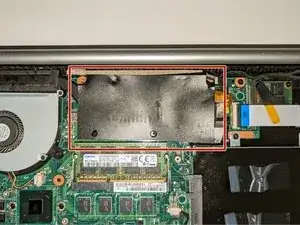
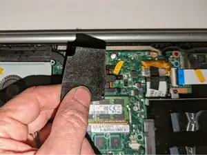
    • Remove the black shield covering the display connector and the heat sink.

    • You may need to use double-sided adhesive tape to resecure the shield.

  5. 1tAZ6LUkM1uMwZES
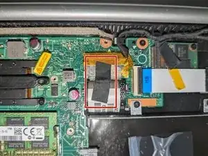
    • Remove the black tape securing the keyboard ribbon cable to the display connector.

    • Fold the ribbon cable the opposite way, resecuring it to the hard drive to keep it out of the way.

  6. fADllA6eMt6YmOUi
    fADllA6eMt6YmOUi
    D1eKElAm3FqpFMuS
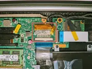
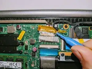
    • Peel off the clear tape from the motherboard display connector.

  7. WC6PBUSTUEVX4Obd
    WC6PBUSTUEVX4Obd
    DPSoHu5NT2WKw1an
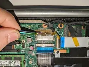
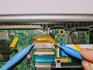
    • Position spudgers on the white tabs on either side of the connector and push evenly to unplug the display.

  8. vYFwdOvtd3ZkMlWw
    vYFwdOvtd3ZkMlWw
    qbmitiyAuJoEN2xC
    JVEnbaUKCrDWml6Z
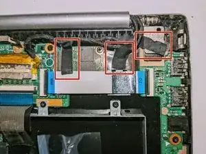
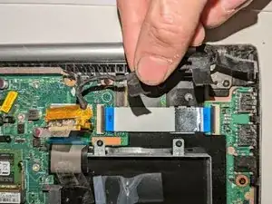
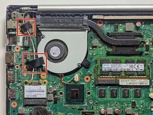
    • Peel off the three pieces of black tape securing the display cable to the motherboard.

    • Deroute the cable from the channel it sits in.

    • Move the cable to the side, out of the way.

  9. N3YU3dNgJObCC6ul
    N3YU3dNgJObCC6ul
    QwZbyDt631I5orO6
    LhLaEceHE3q1SbpB
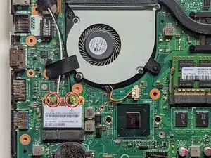
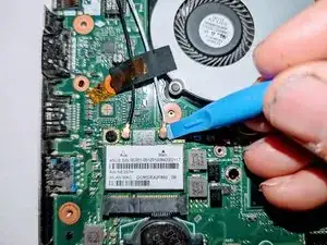
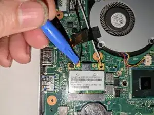
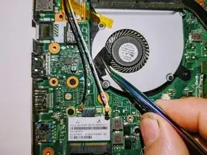
    • Use a spudger to release the cables from the wifi card.

  10. 1QtNUNJKZMsqNQM4
    1QtNUNJKZMsqNQM4
    1YXZ2dvViqOY2dkV
    P1UwZbLWGRFexAAq
    • Lift the tapes securing the wires to the motherboard.

    • Move the wires to the side out of the way.

  11. gUZhPHXwcT6elKHS
    gUZhPHXwcT6elKHS
    NMaik3RfJ6c2xXZJ
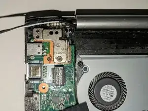
    • Remove the two screws securing the hinge on the left.

    • Pry the hinge up by hand to a 90 degree angle.

  12. ehcNfxjdKUrJEK2m
    ehcNfxjdKUrJEK2m
    pXUi1r43xydu2cih
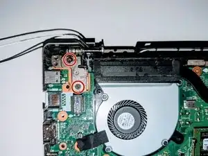
    • Remove the two screws securing the hinge on the right.

    • Pry the hinge up by hand to a 90 degree angle.

  13. FXvUKISYNUuN3qaj
    FXvUKISYNUuN3qaj
    bAjZgyrYkMtEc2ld
    Rxd1MWHNdokonQk5
    • Lift the base of the laptop from the front.

    • Raise it to a 90 degree angle.

    • Slide it forward slightly to clear the hinges.

    • The display is now free.

  14. fH6tBJDoOnlpOwts
    fH6tBJDoOnlpOwts
    YP6fi3LUUclpYdpP
    ma6QTxIT6WlogsdG
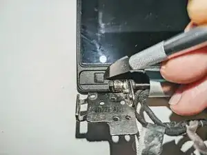
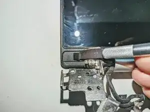
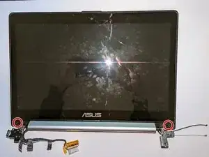
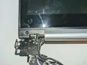
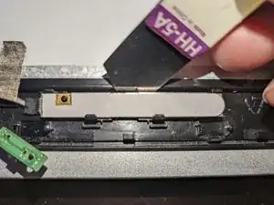
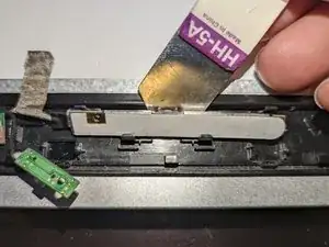
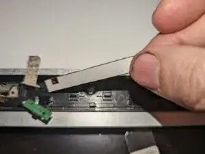
    • There are two black square plastic tabs covering the retaining screws. The tabs are fixed in place with light adhesive.

    • Using a thin blade, pry off the tabs covering the screws.

  15. VbhTgqgbwOrqSWG4
    VbhTgqgbwOrqSWG4
    eeAgDmyXF2daJRK4
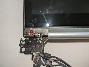
    • With a Phillips #0 screwdriver, remove the two 3.8 mm screws holding the bezel in place.

  16. TKnOqeSYgtCClxUp
    TKnOqeSYgtCClxUp
    ojFGWdviqnfBKafS
    VjRYASFIxybHEmmm
    • Grasp the hinge cover and slide it to the right. It will only move about 3mm (1/8 inch).

  17. 3VHMFnZoEUNkJuOH
    3VHMFnZoEUNkJuOH
    3nEsRETxJLfIwSGH
    • Tilt the hinge cover toward you and pull up to remove it.

    • It may catch on the parts it's covering as you remove it. If that happens, just wiggle it around until it comes free.

    • No force should be needed to remove it. You do not have to pry on it to take it out.

  18. FmRCVEATCjvWNNZJ
    FmRCVEATCjvWNNZJ
    KFyT41c2atuOPau2
    • Slide the screen down to release the catches holding it in place.

    • It will only move about 3mm (1/8 inch) and will stop when it has moved sufficiently.

  19. YZG4e5NbxuADWe4r
    YZG4e5NbxuADWe4r
    dY4RIksFsrJHmufv
    PE65dhMFfOdeXtnO
    • Lift up on the now-exposed bottom edge of the screen. Go around the edges, lifting it away from the housing. If it is still caught anywhere, remember to slide it down to free it.

    • Again, no force is needed. You do not have to pry on it to take it out. Doing so will damage the housing and/or the bezel.

    • Slide the screen out from under the hinges and remove it.

  20. S5ONsBYUADyWRo2K
    S5ONsBYUADyWRo2K
    Cy2wBOf4NjsXSh3a
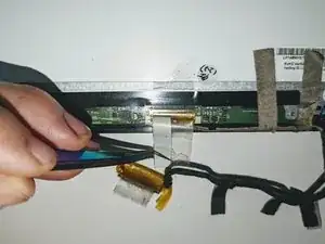
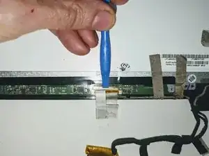
    • Flip the touch screen assembly over and peel the clear tape covering the LCD connector off the LCD panel.

  21. Sa2n2AQannS3GfO1
    Sa2n2AQannS3GfO1
    uGNGSkBFLcSuRkkO
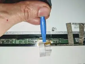
    • Using a spudger, slide the connector out in the direction of the bottom of the screen.

  22. MUUOYX4u6TYTSvMv
    MUUOYX4u6TYTSvMv
    ScC1js2hggumP5aC
    a1be21LHJpBPgqmN
    • The next few steps are easier if you rotate the display so the top of the screen is facing you.

    • Peel off the tape providing a ground point to the LCD frame.

    • Use the flat end of a spudger to flip up the latch on the right connector.

  23. 1jcnYMy2RGCAxZv6
    1jcnYMy2RGCAxZv6
    AGPihRofUZKL1NLt
    • Use the flat end of a spudger to flip up the latch on the left connector.

  24. 3my5sgZJ6nAGoyvy
    3my5sgZJ6nAGoyvy
    iTipjRJfrlOeUmpV
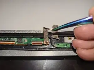
    • Use fine tip tweezers to slide the right ribbon cable out of the connector.

  25. RkdlGMhsst1IVwTw
    RkdlGMhsst1IVwTw
    XOA1QxOuq6FtaHCM
    • Use fine tip tweezers to slide the left ribbon cable out of the connector.

  26. WcI3IpcJOyVN6mEo
    WcI3IpcJOyVN6mEo
    DYFGSFK1dkpaTTeb
    mqxE2bsrZ4LKMxLD
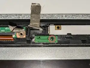
    • The touchscreen board is secured to the bezel with two latches on the far side and a plastic hook on the near side.

    • Use a spudger to open the right latch while gently prying up with an opening tool or a fingernail.

    • Use a spudger to open the left latch while gently prying up with an opening tool or a fingernail.

  27. YymyEKnCmZPIlXHI
    YymyEKnCmZPIlXHI
    RiePVTWaGBBnaq2G
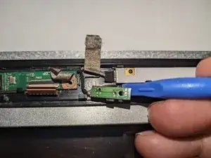
    • Rotate the board toward you while sliding it forward slightly to free it from the bottom hook.

    • Lift the board away from the bezel and move it aside.

  28. hBwCRMm46gi1EFSB
    hBwCRMm46gi1EFSB
    RKPgMCVlp1RKocis
    • The microphone daughterboard is held in place by being pressed down onto a plastic pin.

    • Pry it up off the retaining pin with a plastic spudger.

  29. AVIQBEYkITe6tUxw
    AVIQBEYkITe6tUxw
    LmPe3jwsITBVmHDD
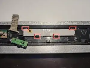
    • The camera daughterboard is held in place with two latches along the top of the board and two hooks on the bottom.

    • It is seated on two plastic guide pins as well.

    • Be sure the board is fully seated on the guide pins when reassembling.

  30. MpM1sADxMSCNrc3j
    MpM1sADxMSCNrc3j
    QRUGHMiHaEyZMcup
    fyxQKC2rO5uICkOq
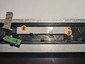
    • Slide a thin pry tool between the top of the camera board and the lip of the bezel.

    • Gently pry up on the board to free it from the latches and the guide pins it sits on.

    • Lift it up and away from the bezel and set it to the side.

  31. bILI1rhKm2KbHMsu
    bILI1rhKm2KbHMsu
    mNTInufhTQfXIoDh
    sLDDfRLEbVuNK53Q
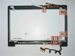
    • Carefully remove the five pieces of conductive tape securing the cables to the LCD frame.

  32. 3dUMgFvuPZvr6kbh
    3dUMgFvuPZvr6kbh
    UNElDgrFtwmPSCU5
    JODpZWjAsDrteLNu
    • Deroute the wiring to the daughterboards from the front bezel.

  33. 4XthKrVRUghIPsNV
    4XthKrVRUghIPsNV
    IMwmjiEA1HWwIXbk
    pnGdBRCcoVsZInuE
    • Deroute the LCD cable from the display.

    • The LCD / digitizer assembly is now free.

  34. GDQIANfQOPyVVIVg
    GDQIANfQOPyVVIVg
    kFE34PRF33UMJegn
    gnOBc1G2cHQUeQHi
    • Heat the front edges of the touch screen with an iOpener, a heat gun or a hair dryer to loosen the adhesive securing the LCD to the digitizer.

  35. JDPEQFiKUQnGNCuW
    JDPEQFiKUQnGNCuW
    3AuPGf6CKfxYn3kM
    tFDx6kDZSUQAXfEc
    • Using a flat metal opening tool, carefully pry up the LCD, inserting opening picks as you go to prevent the display from re-adhering to the digitizer.

    • If you encounter significant resistance, reheat the section you are working on.

    • Start with the top edge of the display.

  36. ltxpZclqpsruwt5R
    ltxpZclqpsruwt5R
    CqixFpAYCrHN6xnI
    VMLXAZO1Toe3AGtP
    • Proceed down the sides of the display and place picks at the bottom corners.

    • Do not attempt to slide an opener under the circuit board along the bottom of the display; you may damage the delicate electrical connectors.

  37. VoheRFUAyOkvHZ5d
    VoheRFUAyOkvHZ5d
    rYhadcjbiSaGPKRW
    HXl4S6OvKxOoWcMH
    • Carefully lift the top edge of the LCD away from the frame.

    • The remaining adhesive on the bottom of the glass will peel off as you continue to lift the LCD.

    • The LCD is now free from the display.

  38. kIWIbcoUbVENIPwp
    • Set the LCD panel aside, being careful not to get fingerprints or dirt on the surface. The digitizer is now free.

Abschluss

To reassemble your device, follow these instructions in reverse order.

See the ASUS VivoBook S400C LCD Adhesive Replacement guide for instructions on how to replace the adhesive tape on the display frame if needed.
Jerry W

Mitglied seit: 21/03/22

30577 Reputation

0 Kommentare