Einleitung
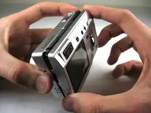
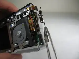
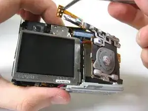
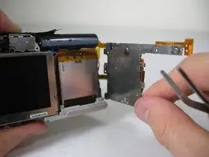
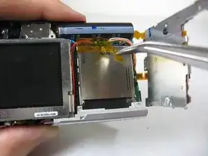
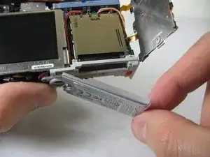
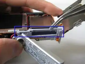
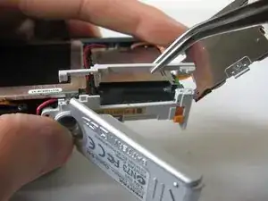
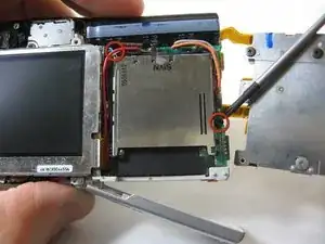
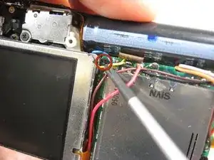
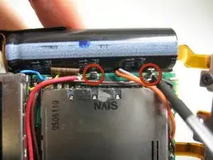
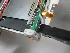
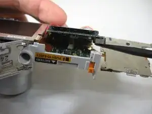
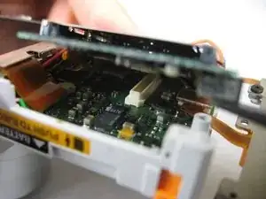
In this guide you will learn how to remove the SD card circuit board to access the logic board. To access the logic board, you will need to unsolder two leads. For soldering instructions, please refer to steps 1 through 6 of this soldering guide.
Werkzeuge
-
-
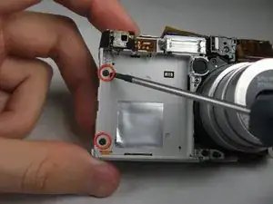
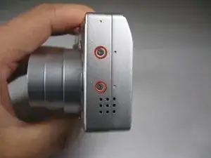
Remove the following screws:
-
Two silver 3.15mm Phillips #00 screws on the right side of the camera
-
Two silver 2.08mm Phillips #00 screws on the left side of the camera
-
-
-
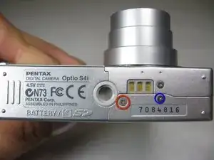
Remove the two indicated screws on the bottom of the camera:
-
The screw circled in red is a longer silver 3.15mm Phillips #00 screw
-
The screw circled in blue is a shorter silver 2.25mm Phillips #00 screw
-
-
-
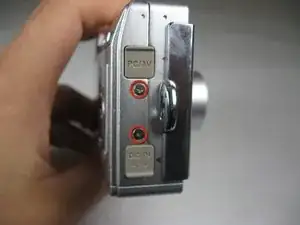
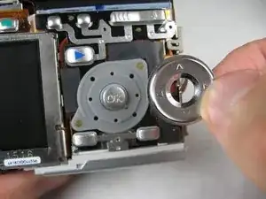
Silver donut-shaped button will fall off. Place separately. Remove the plug covers on the right side of camera, labeled “PC/AV” and “DC IN 4.5V”.
-
-
-
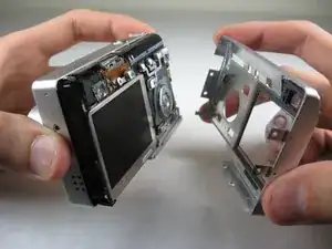
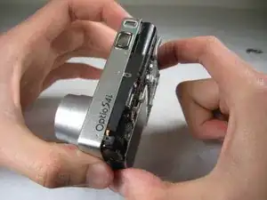
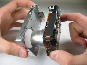
To remove the front cover, gently hold the inside structure of the camera and slowly pull the front cover off.
-
-
-
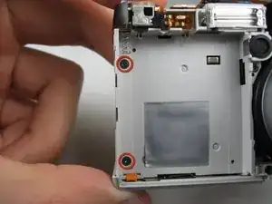
On the front of the camera, in battery case, remove screws indicated:
-
Two black 2.05mm Phillips #00 screws
-
-
-
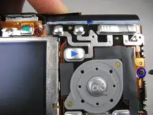
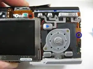
Flip the camera over to the backside and remove screws indicated:
-
The screw circled in red is a longer black 3.00mm Phillips #00 screw
-
The screw circled in blue is a shorter black 2.00mm Phillips #00 screw
-
-
-
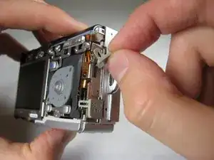
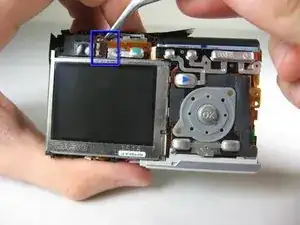
Cautiously and gently pull up the control board at the upper left corner, next to the viewfinder.
-
To reassemble your device, follow these instructions in reverse order.
