Einleitung

This is a difficult guide so make sure you are completely prepared before doing it. Note that thorough removal and cleansing of the old heatsink paste and correct application of the new are vital, otherwise you are likely to make matters worse. Always eliminate a clogged fan or cooling vanes as a cause of overheating before replacing the heatsink paste.

Use of an anti-static wrist wrap is highly recommended. Take care not to use too much force especially for the zero insertion force ribbon cables.

  1. VgBpgRGAoGlBxlfH
    VgBpgRGAoGlBxlfH
    osm3IYEJUGXpHEoO
    LJ644YblBQEFQYAU
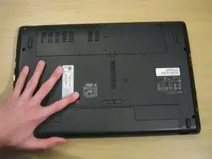
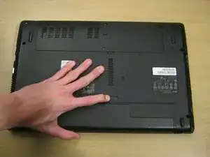
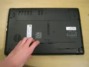
    • Move the battery catch to the "unlocked" position.

    • Pull back the second spring-loaded battery catch until the battery pops up.

    • Remove the battery.

  2. QDVJkH2kLDNI3fcZ
    QDVJkH2kLDNI3fcZ
    UZqIlcpTClhPrrSE
    tFG1ctoWULPBwsYb
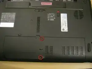
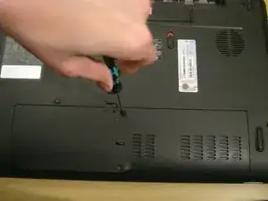
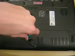
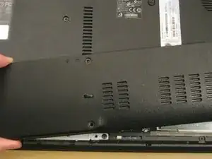
    • Turn the notebook around to face you.

    • There are two Phillips #00 screws securing the cover panel to the rest of the notebook. Remove these screws.

  3. BfhcdSDsYaBJNXCW
    BfhcdSDsYaBJNXCW
    ihrgYVLp14ZvA2JN
    oc3FVRJBQRUYdT3I
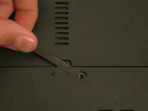
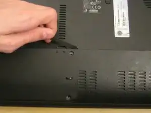
    • Use a spudger to release the panel from the plastic retaining clips keeping it in place.

    • Do not apply too much force, or you may break the clips.

    • Remove the panel and set it aside.

  4. ZtLJy5Fx6Oe6tltu
    ZtLJy5Fx6Oe6tltu
    Mui6LgRNfJnXdGII
    FhbOLyIERNOoTiP1
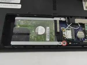
    • Unscrew the Phillips #00 screw which retains the hard drive in place.

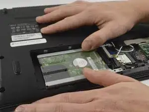
    • Gently slide the hard drive to the left in order to disengage the SATA connectors.

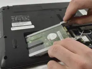
    • It may be quite stiff, in which case you can ease the hard drive out of the SATA connectors by inserting a spudger between the hard drive and the connector block.

    • Lift the drive out of the notebook.

  5. ypavKyYuXCSICUER
    ypavKyYuXCSICUER
    iBCkEEr1TMLe616d
    k24FTGnMFnnIUfPt
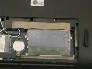
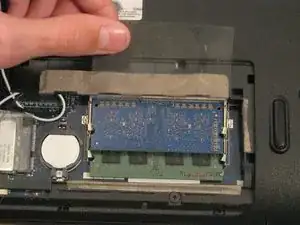
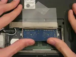
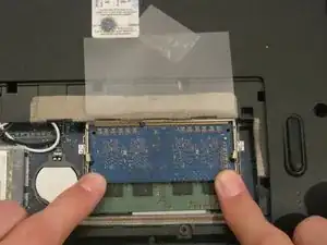
    • The RAM is protected by a transparent cellophane cover.

    • Lift this cover away from the RAM. It will not come free from the RAM.

    • You may wish to use some Scotch tape to hold the cover in place while you work.

  6. NXLCAaIeSgnHEgPW
    NXLCAaIeSgnHEgPW
    rG5VSdZfQg4OHgZW
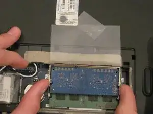
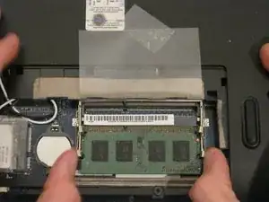
    • Pull back the retaining clips either side of the RAM.

    • It will spring up, ready to be removed.

  7. hd1264LDh5BuIGyl
    hd1264LDh5BuIGyl
    6oyIbCjQLDKKYyCJ
    olxXZOQZUAQN1yCq
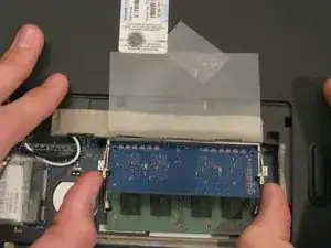
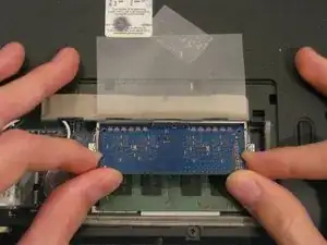
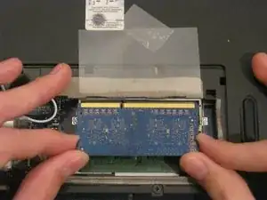
    • Hold on to opposite edges of the RAM chip and gently pull it diagonally upwards to remove it from the computer.

    • Repeat steps 5 and 6 for the second RAM chip if necessary.

  8. P5HaLx3ySrP3ussj
    P5HaLx3ySrP3ussj
    UIMK1oOZrEQZmY1G
    • When reinserting RAM, push it diagonally downwards until almost all of the gold connector strip is inside the socket.

    • Push gently down on the RAM until the retaining clips click back over it.

  9. eQjTWwpwbURNp3ij
    eQjTWwpwbURNp3ij
    GSgdc4MwPL3mWFwU
    huNRpgCOBbSXgQN5
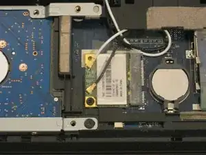
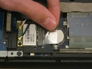
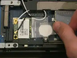
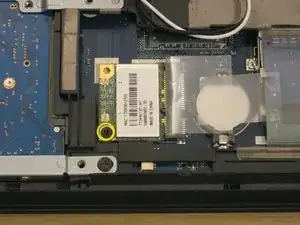
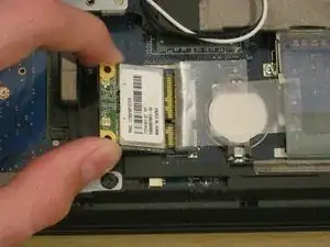
    • The WLAN card is protected by a transparent cellophane cover.

    • Lift this cover away from the WLAN card. It will not come free from the WLAN card socket.

    • You may wish to use some Scotch tape to hold the cover in place while you work.

  10. eumjsLfJefKQYLH1
    eumjsLfJefKQYLH1
    QVQLDltuMJvSOibA
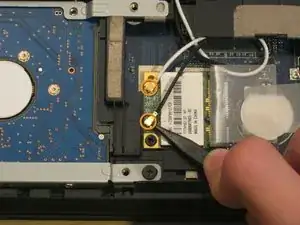
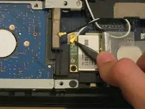
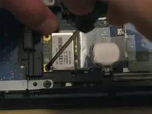
    • Use the pointy end of a spudger to remove the antenna connectors from the WLAN card.

  11. GHiK5iOCXl4v1XiZ
    GHiK5iOCXl4v1XiZ
    NMdN1ExtYybwpBJr
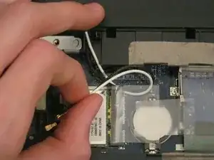
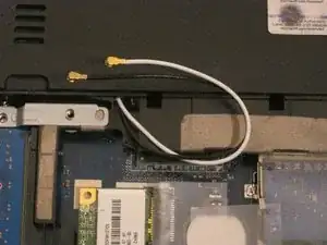
    • You may find it useful to pull the antenna cables out from under the plastic retaining clip so you can move them out of the way while you work.

  12. cYlCHLNsxrJpfdlY
    cYlCHLNsxrJpfdlY
    3deeP3OeZJOPymG2
    DgOimcLASSKSVlSZ
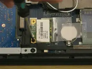
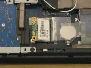
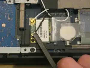
    • There is one Phillips #00 screw keeping the WLAN card attached to the notebook.

    • Remove this screw.

    • The WLAN card will spring up from the notebook at an angle.

  13. OFSEknayAPM13VwZ
    OFSEknayAPM13VwZ
    m2FgdJFPOCZFACvi
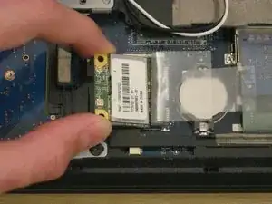
    • Just like RAM, hold the WLAN card by the edges and pull it out at an angle.

  14. V4hrhawdUYE6TrUW
    V4hrhawdUYE6TrUW
    CSIMZYEThqP1VJ2J
    • When you're installing the new WLAN card, you might want to hold it down with one hand while you put the screw in with the other.

    • You might also want to put the antenna cables back in using the flat end of a spudger.

  15. uSJoafsU5UsEhPgU
    uSJoafsU5UsEhPgU
    RXPJ3vYuSCFpHqSY
    s5bw4pcZCeOZ2jBk
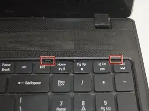
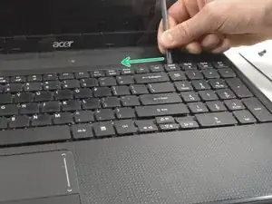
    • Unfold the laptop so that you are looking at the keyboard.

    • At the top right of the keyboard you will notice two clips above the 'Del' and 'End' keys.

    • Using your spudger, press these clips in to unlock the keyboard from the laptop

    • Be careful not to press too forcefully on these clips with the spudger as they may break

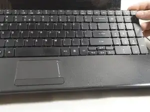
    • Slide the spudger along the top of the keyboard until the keyboard is able to easily be lifted up out of the laptop

    • Do NOT attempt to fully remove the keyboard as there is still a cable on its backside connected to the computer that can be damaged

  16. wCGAFjyL4Gmy5alM
    wCGAFjyL4Gmy5alM
    V3ZvlNHRSHk1xEbi
    NJRkcwqQiqR4Gr2R
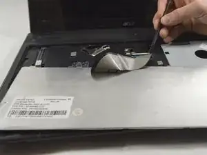
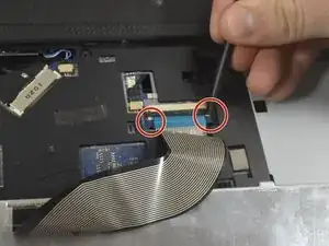
    • Now that the keyboard is outside of the laptop, you will see a ribbon cable coming from the back of the keyboard connected to the laptop.

    • To detach this cable you must use the pointed edge of the spudger to press down on the locking mechanisms on each side.

    • Do not use too much pressure when disconnecting the ZIF connector.

    • After unlocking both sides of the ZIF connector remove the keyboard for replacement.

  17. xce3XO3NJHL3Eh3s
    xce3XO3NJHL3Eh3s
    j4gWYTYCNDv3jvXM
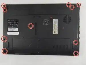
    • Remove the 10 Phillips #0 screws on the bottom cover.

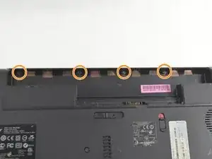
    • Remove the 4 Phillips #00 screws from under the battery.

  18. rYijRecvYMPDdicW
    • Remove the 8 Phillips #0 screws from under the keyboard.

  19. DJvJSEmN1oFeJsq3
    DJvJSEmN1oFeJsq3
    UhaKfd6FOrxfSd1k
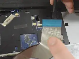
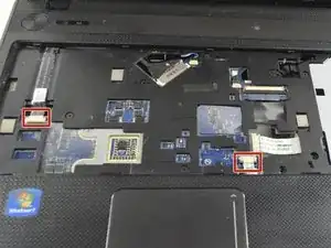
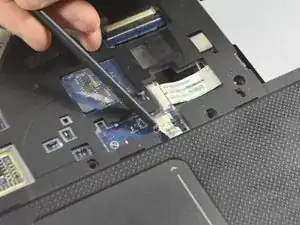
    • Release the two ribbon cables from the ZIF connectors in the same fashion as in Step 11 with the black spudger.

    • Once the mechanism is released you may remove the cable by hand.

    • The plastic cover can now be easily lifted and removed from the rest of the laptop.

  20. 1ZdA6pDblxEYkQK2
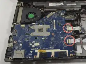
    • Remove the two remaining ribbon cables as described in Step 11.

  21. PplJbF1Ou3RlAncm
    PplJbF1Ou3RlAncm
    HFPNWMTt4NCD6bGi
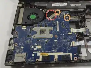
    • Remove the display cable with the spudger by pushing each end of the cable out of the connector until it is loose enough to be pulled out by hand.

    • In a similar fashion as with the display cable use the spudger to remove the two power cables from the motherboard.

  22. Y3kTB2MCrYTRNAgD
    Y3kTB2MCrYTRNAgD
    vd6kAK2RDU6hs6UJ
    DdPXi2rMXYkSPrCM
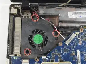
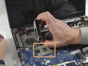
    • Remove the 3 Phillips #0 screws from the fan bracket.

    • Lift the fan up and place it back down above the heatsink.

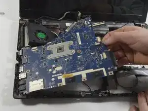
    • Do not fully remove the motherboard. As there is hidden cable on the underside that could be damaged.

    • The heatsink has a strip of adhesive on the underside securing it to the plastic body.

    • The motherboard can be lifted from the side and and then to the right to free the I/O port from the enclosure. Some force may be required to release the heatsink.

    Can you help me out? I’m having trouble lifting up the fan. It seems to be stuck to the metal part near the vent on the side and I can’t figure out how to lift it, Any tips?

    Diego Rios -

    I broke my touch pad zip connecter .Then what can i do ?

    Muhammad Ayub Zahid -

    If it’s the locking bar that’s broken you can sometimes wedge some packing into the connector to enable it to make a good connection with the ribbon. A proper fix would be to fit a new connector, but that would require microsoldering skills which I guess you don’t have. It’s possible you could find a repair shop that could undertake it - quite easy with the right equipment and skills. Undoubtedly the easiest thing is just to forget about the touch pad and use an external mouse instead - many people prefer it anyway.

    Philip Le Riche -

  23. XpeBaueNLkf3cDVL
    XpeBaueNLkf3cDVL
    wrEcjqchrEkxEGK5
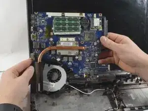
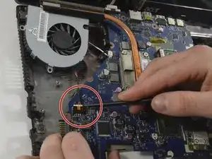
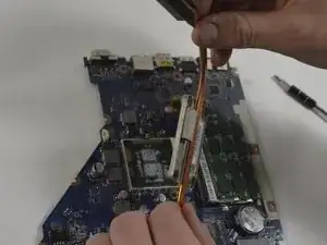
    • Rotate the motherboard to the right and lay it down so that the copper heatsink is facing up and parallel with the bottom of the monitor.

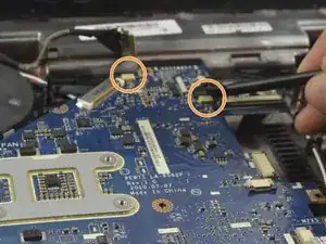
    • In this position the last cable to the motherboard can be disconnected using the spudger to push each end out until loose enough to pull the cable completely out.

    • The motherboard can now be completely removed from the laptop enclosure.

  24. 26aAo3mxMU5Afygy
    26aAo3mxMU5Afygy
    mPkRDa5fCOpIDNcY
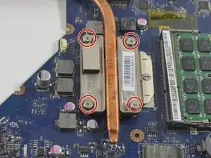
    • Remove the 4 Phillips #0 screws from the heat sink.

    • The heat sink can now be removed from the motherboard and CPU.

    • Follow this great guide to re-apply your thermal paste- Wie trage ich Wärmeleitpaste am besten auf

Abschluss

To reassemble your device, follow these instructions in reverse order.
Claudia Torres

Mitglied seit: 21/10/16

818 Reputation

0 Kommentare