Einleitung
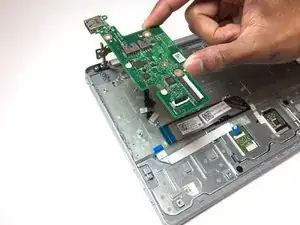
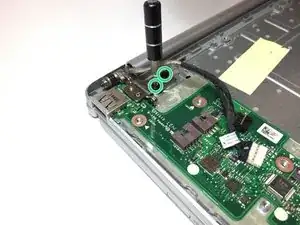
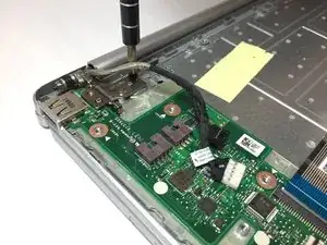
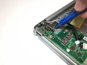
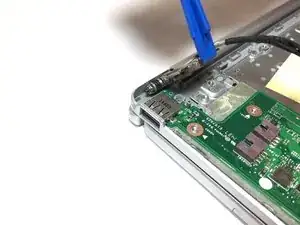
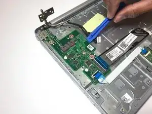
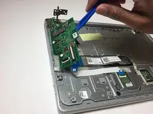
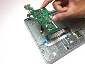
If a USB device is plugged-in correctly into the USB port and the Acer Aspire Switch 10 does not detect the USB device, then you may need to replace the USB port. Before you attempt to replace the USB port, please make sure that you have visited the troubleshooting page and followed the recommendations on the page. The troubleshooting page recommends that you make sure the USB device itself is working properly and that the USB port is clean. If you have attempted everything that the troubleshooting page recommends and the USB port still is not working properly, this guide will help you replace the USB port.
Werkzeuge
-
-
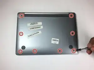
Remove the 8, 5.25 mm screws on the back cover using the screwdriver.
-
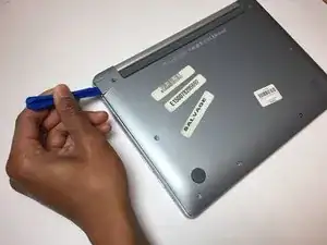
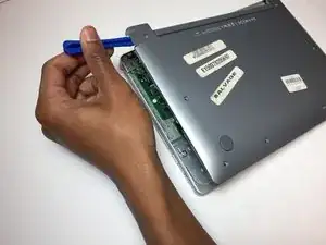
Carefully remove the back cover using the opening tool.
-
-
-
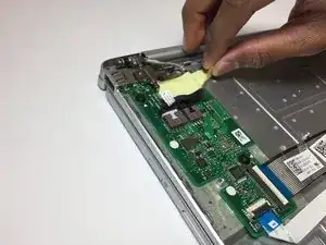
Remove the yellow tape from the circuit board that is connected to the USB port.
-
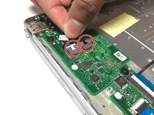
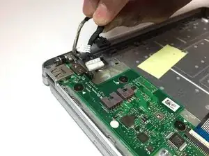
Carefully unplug the two bundled cable connectors by pulling on them.
-
-
-
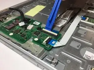
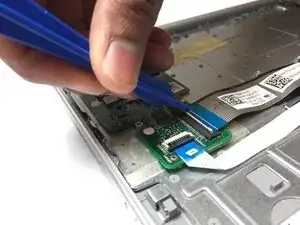
Flip up the ZIF connector that holds the larger ribbon cable in place with the opening tool.
-
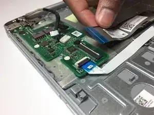
Carefully unplug the larger ribbon cable by pulling on its blue tab.
-
-
-
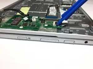
Flip up the small ZIF connector that holds the smaller ribbon cable in place with the opening tool.
-
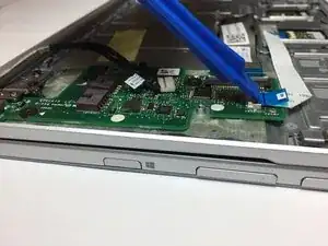
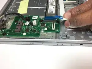
Carefully unplug the smaller ribbon cable by pulling on its blue tab.
-
-
-
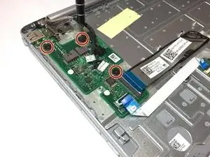
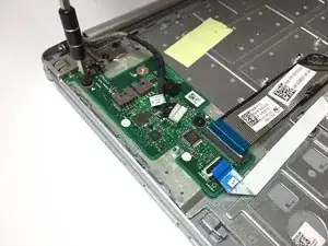
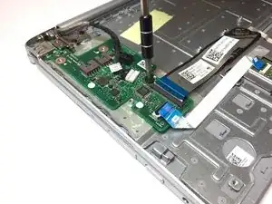
Lift the security tab so that it will be out of the way when you remove the circuit board.
-
To reassemble your device, follow these instructions in reverse order.
