Einleitung
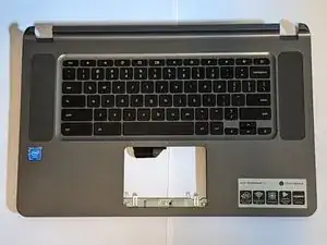
Many Acer 15" Chromebooks use the same keyboard, including the C910, CB3-431, CB3-531, CB5-571 and possibly others, although the palm rest assembly is the same only on the CB3-531.
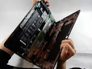
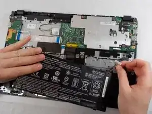
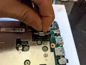
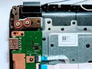
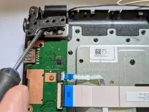
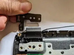
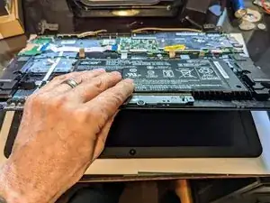
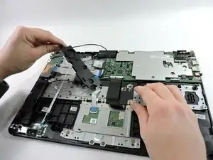
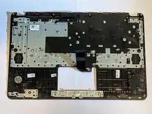
There are new keyboard-only replacement parts for sale, but using them requires melting off or otherwise removing the head of approximately 58 plastic retaining pins, then figuring out how to re-secure them. That kind of replacement is beyond the scope of this guide, so we'll only be dealing with a replacement that comes with a keyboard + palm rest as a single unit as pictured above.
Werkzeuge
-
-
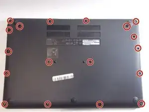
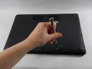
Using the Phillips #1 screwdriver, remove eighteen 7 mm screws from the back panel of the device.
-
-
-
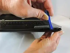
Use a plastic opening tool around the edges of the laptop and remove the back panel from the device.
-
-
-
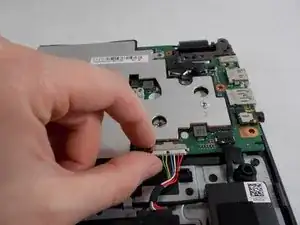
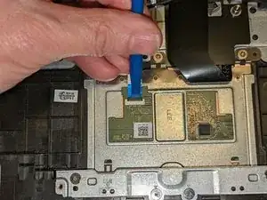
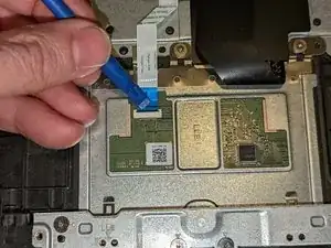
Push on the sides of the connector with a plastic spudger to separate the cable from the motherboard.
-
-
-
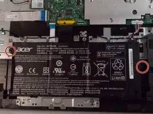
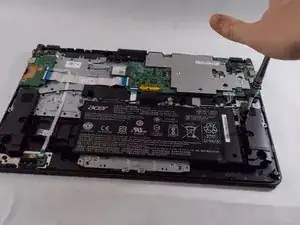
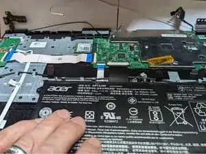
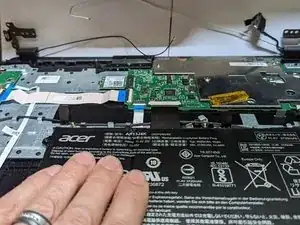
Using the Phillips #1 screwdriver, remove the two black 5.5 mm screws securing the battery.
-
-
-
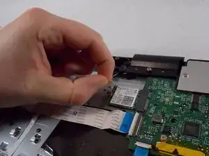
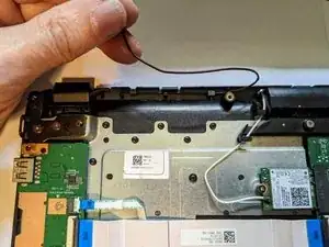
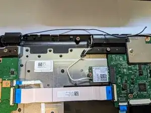
Firmly pull the end of the black wire attached to the Wi-Fi card upwards and remove it from the device.
-
Repeat with the white wire.
-
-
-
Pull the end of the display cable attached to the motherboard straight up to remove.
-
Rotate the cable out away from the motherboard.
-
-
-
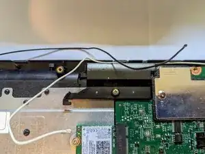
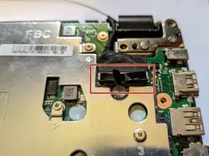
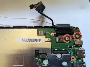
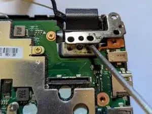
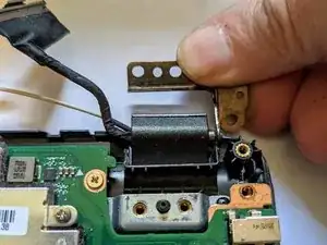
Insert a screwdriver or spudger under the hinge to get it started then rotate it open by hand as far as possible.
-
-
-
Insert a screwdriver or spudger under the hinge to get it started then rotate it open by hand as far as possible.
-
-
-
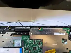
Lift the palm rest assembly from the front then slide it away from the hinges slightly to remove the assembly from the display.
-
-
-
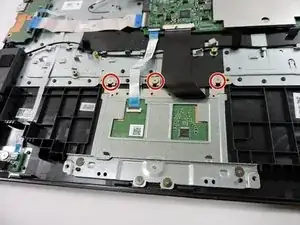
Using the Phillips #1 screwdriver, remove the three 3.2 mm screws holding the touchpad to the laptop.
-
-
-
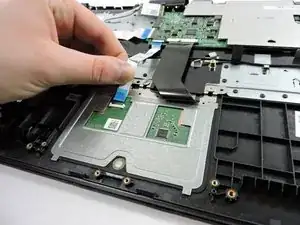
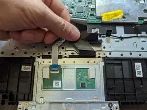
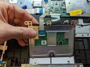
Carefully lift up on the keyboard ribbon cable and the insulating sheet immediately below it so the touchpad can clear them.
-
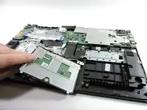
Lift the touchpad slightly from the top.
-
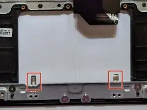
Pull the touchpad toward the motherboard as you continue to lift it, sliding it out from under the retaining fingers at the bottom.
-
-
-
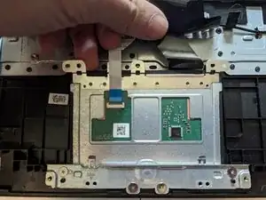
Remove the touchpad.
-
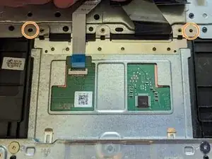
Make sure the touchpad goes underneath the two retaining fingers when reinstalling it.
-
The touchpad is correctly aligned when the guide pins next to the left and right screws are inserted in the holes.
-
-
-
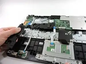
Thread the speaker under the black ribbon towards the left to allow removal of the left speaker.
-
-
-
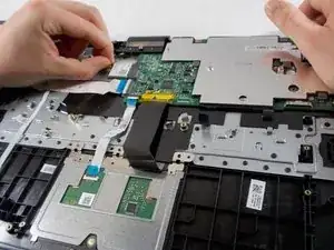
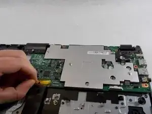
Peel the yellow tape off the black keyboard ribbon cable on the motherboard.
-
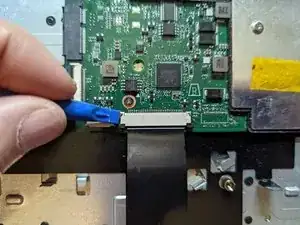
Use a spudger to slide the black tabs on either side of the connector forward slightly.
-
Pull the black ribbon straight towards you to remove it from the motherboard.
-
-
-
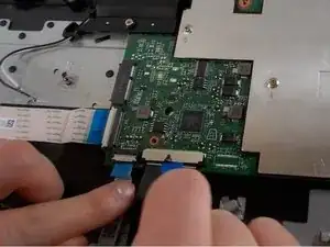
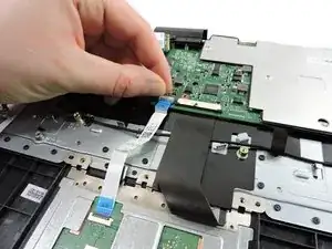
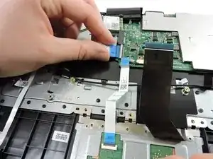
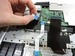
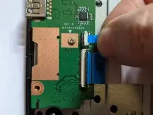
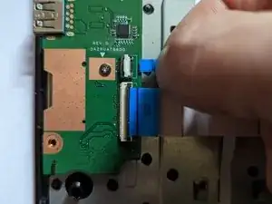
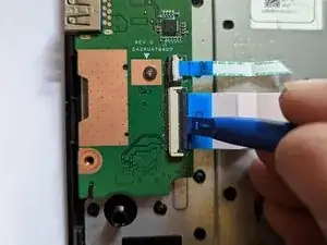
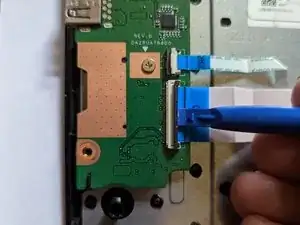
Flip up the tabs over the two white ribbons on the left using your finger.
-
Pull the ribbons out of the motherboard by the blue tabs.
-
-
-
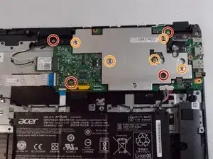
Using the Phillips #1 screwdriver, remove four 6 mm screws.
-
Using the same Phillips #1 screwdriver, remove five 3 mm screws securing the metal plate to the motherboard.
-
-
-
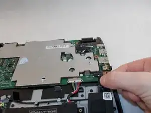
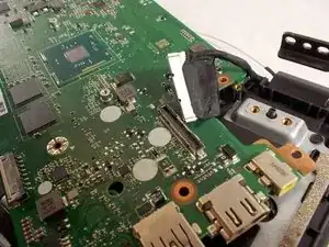
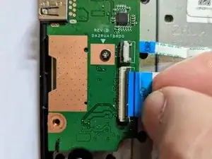
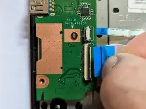
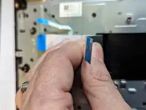
Grasp the ribbon cable by the blue plastic reinforcement and pull the cable straight out to the right.
-
-
-
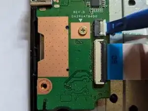
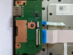
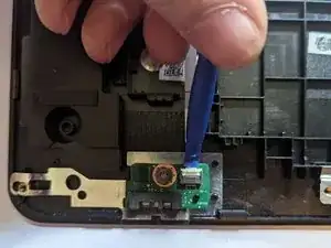
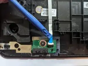
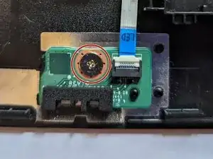
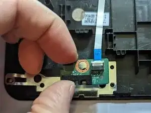
Remove the single retaining screw securing the LED board.
-
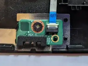
Remove the board.
-
When reassembling, ensure the board is seated on the guide pin before reinstalling the retaining screw.
-
-
-
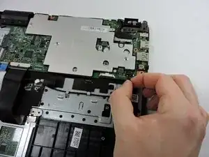
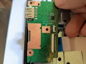
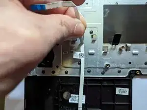
The cable between the I/O board and the motherboard is lightly adhered to the plastic insulator on the keyboard. Pull up from the right to free the cable from the adhesive.
-
-
-
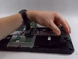
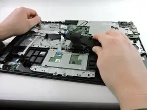
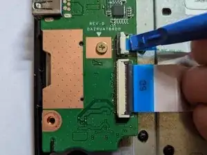
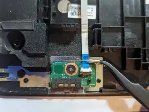
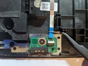
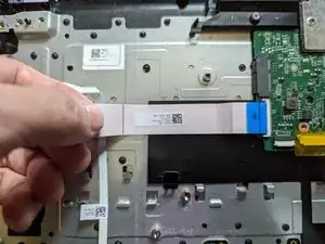
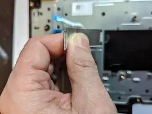
The LED cable runs from the LED board to the I/O daughter card. It is lightly adhered to the keyboard. Remove it by gently pulling it away from the keyboard.
-
To reassemble your device, follow these instructions in reverse order.
