Einleitung
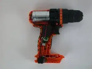
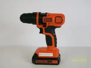
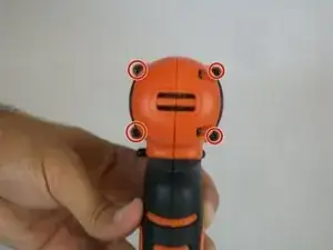
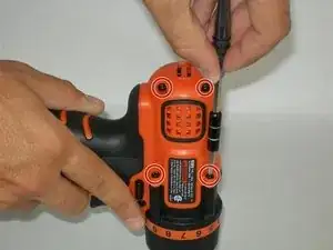
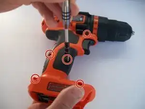
One of the reasons you would replace the safety switch is if it does not alternate between the on and off position. The switch could be stuck or jammed, If this is the case then we would need to replace it. Some of the tools needed to repair this will be a soldering iron and soldering flux. In order to complete this repair, some soldering skills will be required.
Werkzeuge
-
-
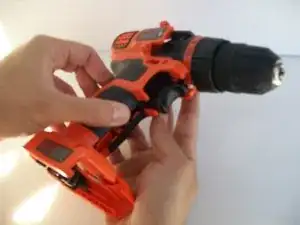
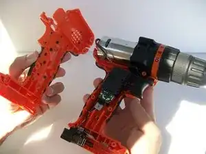
After following the prerequisite guide, the interior components of the drill can now be accessed.
-
-
-
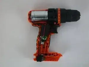
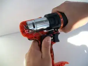
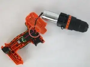
Gently remove the chuck and motor assembly from the drill case.
-
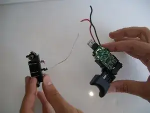
Disconnect the wire connecting the motor and trigger chip.
-
-
-
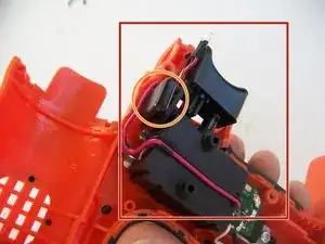
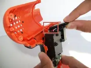
Check if the safety switch is jammed or broken.
-
If jammed, move any wires or other objects blocking the switch's path.
-
If broken, replace the safety switch.
-
-
-
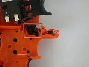
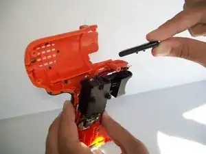
To replace, gently remove the old safety switch from the drill casing.
-
After the old safety switch has been removed, a new one may be inserted.
-
-
-
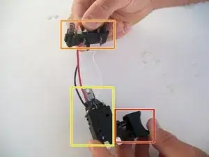
The trigger is indicated by the red box.
-
The battery connector is indicated by the orange box.
-
The trigger chip is indicated by the yellow box.
-
-
-
Remove trigger chip panel to access wire connections to the chip.
-
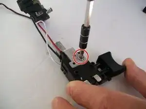
Using a Phillips head screwdriver, remove the screws as indicated.
-
-
-
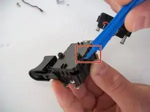
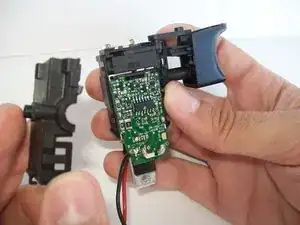
After prying open the chip compartment, the connections will be visible.
-
Check the connections for damage or disconnection. Reattach as necessary.
-
If the connections do not seem to be damaged, the chip itself may be broken and must be replaced.
-
-
-
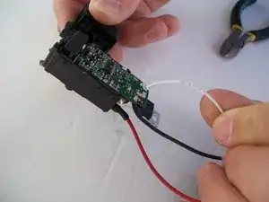
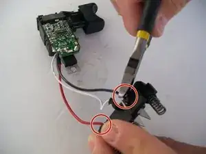
To replace trigger chip, remove wire connections between battery connector and trigger chip using a pair of sidecutters.
-
To reassemble your device, follow these instructions in reverse order, re-soldering wires where necessary.
Ein Kommentar
where can i get a trigger chip from?
