Einleitung

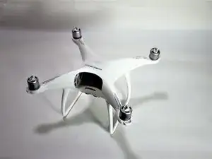
If you have a damaged or malfunctioning motor, this guide will lead you step by step on how to replace those motors. For this guide you will need a soldering iron.

  1. AcVnCikssxi1Unqa
    AcVnCikssxi1Unqa
    dbUEVqWlOIUfjrmR
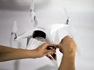
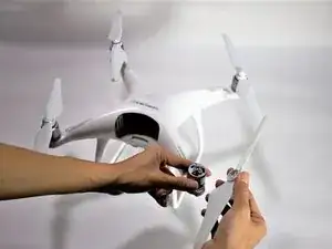
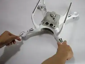
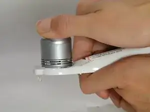
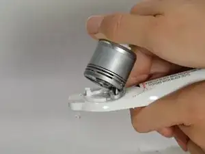
    • Use your finger tips to pinch the damaged propeller.

    • Twist the propeller counterclockwise and pull up to remove.

  2. pIFgeNLgDXZgjM6U
    pIFgeNLgDXZgjM6U
    l14q5bMgvSlL31lR
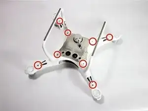
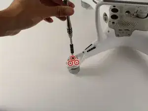
    • Remove the eight 7 mm hex screws by turning counterclockwise with a 2 mm hex bit.

  3. hYs5eKq5BYWcADjF
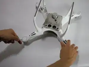
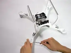
    • Pry the LED motor covers off with a metal spudger.

    • The prying location is marked by an indent that points outward from the arm.

  4. 56nSmabEaeJfgGau
    • Pry the paper covering off the four corners with a metal spudger.

  5. TeTfJj1YEhwkAeyL
    • Remove the twelve 8.7 mm hex screws with a 2 mm hex bit from the motor bases.

  6. fMZHq1UFv2GOTwQd
    fMZHq1UFv2GOTwQd
    JnPCkVciPbDdfj4w
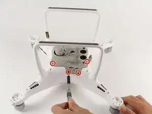
    • Flip the drone on its back

    • Remove the eight 4.5 mm hex screws by turning them counterclockwise with a 1.5 mm hex bit.

    • Separate the mesh from the drone by pulling up gently and rocking left to right.

    • The cable connects from the camera to the drone. Pulling up could rip the connection. Tilt the mesh 90 degrees towards the cable.

  7. UxeyoYUahJ2Ndqbi
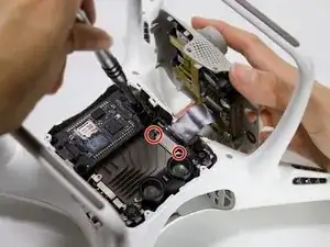
    • Remove two 1.2mm screws using the JIS #000 bit from the camera cable retaining bracket.

  8. WSe2ODujb1mQUHTY
    • Lift the camera connector at one end with your hand and remove the mesh.

  9. nE2LZZeWAc5AFB2k
    nE2LZZeWAc5AFB2k
    YfhiTgEMbcH5eeDy
    tFFtF5kThfkr2N3n
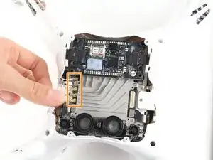
    • Remove the two 1.2 mm screws using a JIS #000 bit from the antenna retaining bracket.

    • Pull the four U.FL antennae up.

    • The U.FL antenna connectors are fragile.

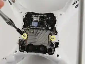
    • Remove the two 4 mm screws using a JIS #000 bit.

  10. gIrCkFeCAuZDRCTI
    gIrCkFeCAuZDRCTI
    VcPZiEBOoOE3BMU5
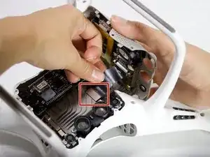
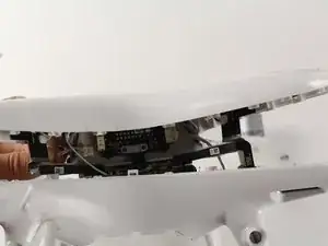
    • Pry apart the clamshell at the motor end.

    • Separate the clamshell.

    • Two wires connect from the lower frame to the upper frame at the front of the drone. Pulling the clamshell apart hard may damage the connectors and wires.

  11. rAnhgEVcqJuNnJrX
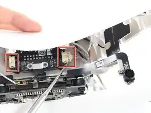
    • Press the connector tabs with a spudger and pull on the wire simultaneously.

    • Remove the shell from the rest of the drone.

  12. fx2RXWwjpOt6svZS
    fx2RXWwjpOt6svZS
    bl4WByjZRQAJTF6u
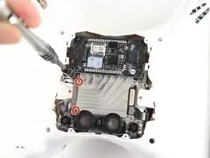
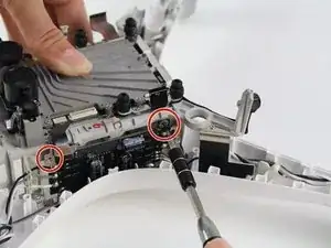
    • Remove the two 4 mm screws using the JIS #000 bit.

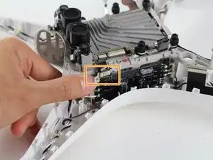
    • Flip the metal bracket to the right and slide up.

    • Take care when handling the metal bracket because it can easily break off.

  13. g2YPktfk46BIAOYT
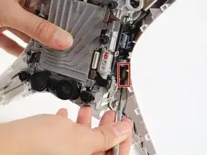
    • Unlodge the glue from the board using a metal spudger.

  14. trDClBtLlMIgYXpK
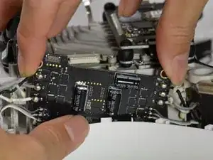
    • Jiggle the electronic speed controller board up and away from the drone.

  15. es2amTQaKnpUUJoL
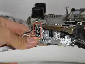
    • Desolder the motor and LED wires on both sides of the board. For general soldering information, visit this Soldering Technique Guide.

  16. CVj24an2ujRJAYvV
    CVj24an2ujRJAYvV
    ohkXlmkFEIfBlPKQ
    • Pry the motor away from the arm.

    • Pull the motor and the motor wires out of the body.

Abschluss

To reassemble your device, follow these instructions in reverse order.
David Albarran-Martinez

Mitglied seit: 08/10/18

260 Reputation

0 Kommentare