Einleitung

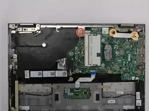
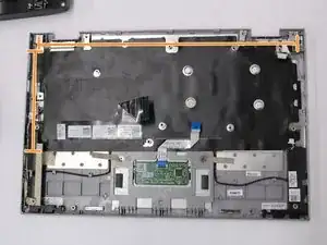
This guide is intended to demonstrate the removal and replacement of the keyboard in the Dell Inspiron 3148. The procedure may be missing some steps. In Step 21, most of the components have been removed from the keyboard/case assembly. However, the speakers and trackpad still remain, and can be replaced on the keyboard/case assembly if salvageable. Furthermore, it is possible the keyboard can be removed from the case and replaced independently. If you find this to be the situation, consider revising this guide to include the additional steps. Thanks!

  1. rBoWkmLjKIEWoKbK
    rBoWkmLjKIEWoKbK
    JKwXJnTyf5NiZJxG
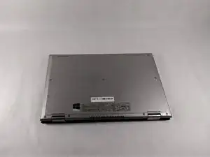
    • Ensure the device is powered off and unplugged. Close the device and orient it face up, with the hinges further away from you.

    • Flip the device over so the backside is facing you.

  2. hNnxvqZkr5B1MKl6
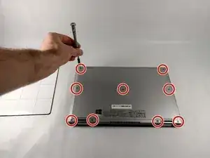
    • Using the Phillips #1 screwdriver, remove all nine 7mm screws.

  3. NJsHhBGIXyxNB6hQ
    NJsHhBGIXyxNB6hQ
    uKpdoJJTLPaQefGl
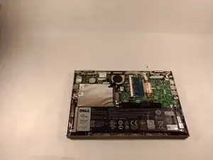
    • Using the plastic opening tool, pull the back panel upward. Move the opening tool along the edge of the device and lift the panel off of your device.

    • Be aware, the back panel is kept in place by magnetic clips. They will offer some resistance, but continue to gently leverage upwards.

  4. uakTaQ1bdR1BeKdU
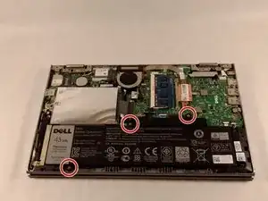
    • Remove the three 4mm screws holding battery in place using the Phillips #0 screwdriver.

  5. p2BdLkFcLswLO2Ur
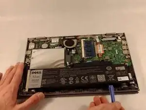
    • Using the iFixit opening tools, lift the battery out of its housing.

  6. REWkJTDAkyNVJbaY
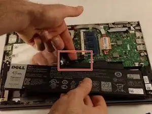
    • Once loosened, use your fingers to lift the battery up and out of its housing.

    • There is a small cable which sits in a rut in the top of the battery. Ensure that it is pushed out of the way before removing completely.

  7. 5hVaCgB2nnfIHTD6
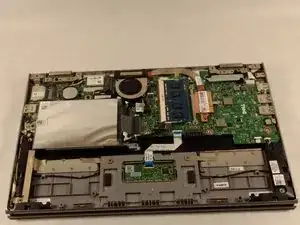
    • Remove the battery completely.

  8. Iof3Kcpepal4NFHE
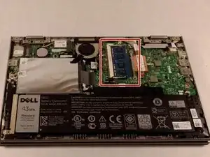
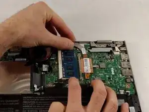
    • Locate the RAM chips on the motherboard.

  9. 4cGLBFDvLEaVa5Zc
    • There are two tabs on either side of the RAM chip. Pull them away from the chip.

  10. MrVGRZtQOuUsSwPT
    MrVGRZtQOuUsSwPT
    wmdPsICBAcEyJPQX
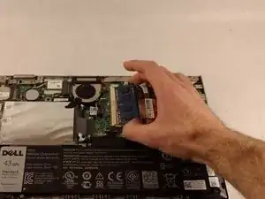
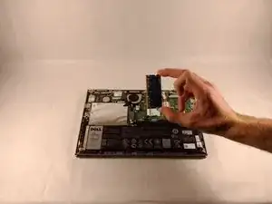
    • The RAM chip will pop up out of the slot.

    • Pinch the RAM between two fingers, making minimal contact. Gently pull away from its port.

    • Remove the RAM from the device.

  11. AoIw32rCSidebDbS
    AoIw32rCSidebDbS
    Bd3AmCPhTHfBNMku
    dVnsnKaZj2iUpXeT
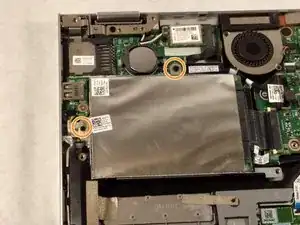
    • If there is a piece of tape connecting the hard drive and a small power cord, remove the tape.

    • Using the Phillips #0 screwdriver, remove the two 4mm screws.

  12. cWXIpAFPBwyhMjtC
    cWXIpAFPBwyhMjtC
    jgAFidf2YWjCDRsj
    RIEBFODVQIxwSyQN
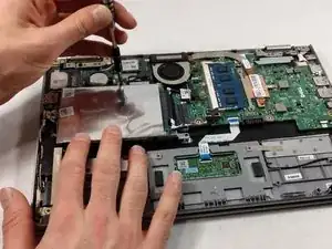
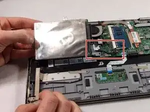
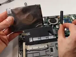
    • Notice: there is a small data cable connecting the hard drive to the motherboard. Do not attempt to lift the hard drive all the way out before removing this cable.

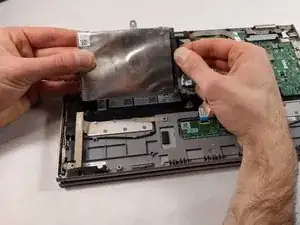
    • Lift the hard drive slightly out of the device.

    • Grasp the head of the cable, not the cable itself.

    • Pull away from the hard drive, removing the data cable. The hard drive may now be fully removed.

  13. cwSHxIdYpjRcPAWB
    cwSHxIdYpjRcPAWB
    FcqBlTMuIAu5NCLb
    sL4QPMgPtQx2xxiC
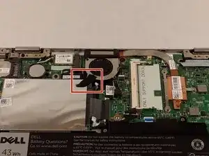
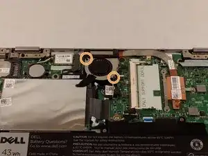
    • If there is tape on your fan, remove the tape.

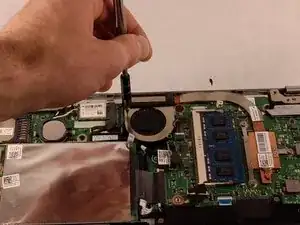
    • Remove the two 2mm screws on the fan enclosure using the Phillips #00 screwdriver.

  14. ejGHDw3JS4i1AdiB
    ejGHDw3JS4i1AdiB
    konw6cTlGeGc5xDp
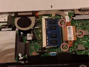
    • Unscrew the three 4mm screws holding down the heat sink of the fan using the Phillips #00 screwdriver.

    • The three 4mm screws found in the heat sink will remain attached to the heat sink. This is okay as long as they are detached from the motherboard.

  15. NuQ5KyMxcaZvaCpV
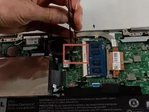
    • Use the tweezers to gently pull the power supply cable from its port.

  16. JoW1ptwJR1JrJWRF
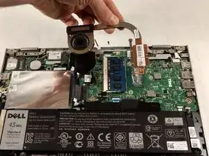
    • Grasp the fan and lift upward. Remove the fan from the device.

  17. RV31RqQygmQWUNgU
    RV31RqQygmQWUNgU
    fLbUFrYWPKImIRvq
    ZqFVIN51CsifhEP1
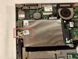
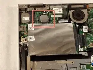
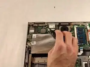
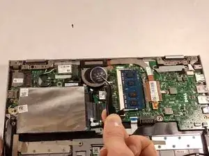
    • Using a pair of tweezers, lift the exposed edge of the CMOS battery upward.

    • Once the CMOS battery has been loosened, remove it from the device.

  18. YMrS3XVDCefqO6Da
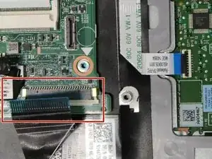
    • Remove the keyboard cable from its ZIF connector by flipping up the locking tab on the connector and then pulling the cable out.

  19. OlDEkqTHF3aQVQbf
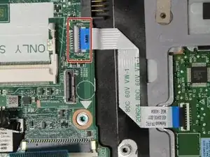
    • Remove the touch pad cable from its ZIF connector.

  20. 1aGygRo2SlOH52Un
    • Remove one 3.41mm screw using a Phillips #000 screwdriver.

    • Remove the two 3.41mm screws using a Phillips #000 screwdriver.

    • Remove motherboard.

  21. Lvr1eJHNySOyPEtF
    Lvr1eJHNySOyPEtF
    HEXDIUheqT3hMEKb
    • Using a Phillips #000 screwdriver, remove single 4.1mm screw from the SD card reader board.

    • Remove the SD card reader board.

    • Remove the keyboard.

Abschluss

To reassemble your device, follow these instructions in reverse order.
Wesley Taylor

Mitglied seit: 02/10/19

73 Reputation

0 Kommentare