Einleitung

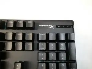
This guide will show how to replace the mechanical key switch LEDs from your HyperX Alloy Origins mechanical keyboard (serial number HX-KB6RDX and its variants).

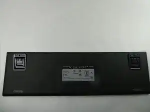
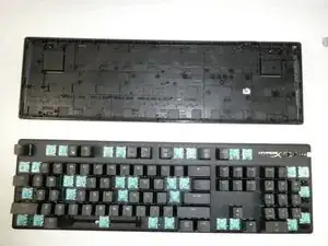
The HyperX Alloy Origins mechanical keyboard provides RGB lighting to each of its keys through switch-mounted LEDs. Therefore, it is necessary to remove an entire key switch whenever its corresponding LED needs to be replaced.

Before beginning LED replacement, be sure to visit the troubleshooting page before making permanent changes to the PCB! This guide should only be used in the event that one or more keys do not light up while the remaining key LEDs are properly functioning.

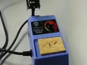
Usage of a desoldering iron or a desoldering pump (alongside a normal soldering iron) is strongly recommended. The HyperX key switches contain pins which make it difficult to wick away solder. This guide uses a sole soldering iron for demonstration purposes only.

  1. tq41MSXRQK1lEwCR
    • Locate the toggle indicator tab on the top right corner of the keyboard.

  2. vP2Jja3EMbncTtPK
    vP2Jja3EMbncTtPK
    uIpYafeQDTYY5S3d
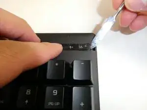
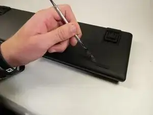
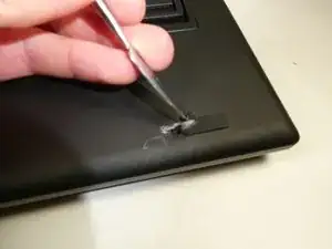
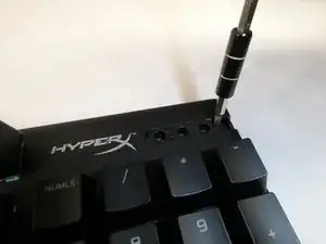
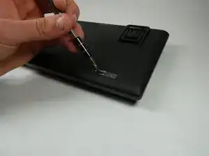
    • Insert the metal spudger or some other separating instrument into the right crevasse between the tab and the keyboard.

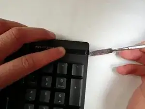
    • Lift up gently on the tab, while holding the left side of the tab down.

    • The tab can spring upwards upon removal. Eye protection is recommended during this step.

  3. jegHiO5lBMsGCiy2
    jegHiO5lBMsGCiy2
    aFIiHrE2LeuGAk4U
    • Flip the keyboard over so that the backplate is facing you.

  4. uede36YxbIcBqxLY
    uede36YxbIcBqxLY
    IHHD5kBMn3FfEBvP
    cQW1NLNERQD4PSZu
    • Remove the rubber feet on the four corners of the backplate.

    • When reassembling, use an adhesive to reattach the feet. A silicone rubber adhesive is recommended.

  5. p4upmknuNikyQAPS
    p4upmknuNikyQAPS
    KGmAane1vZcd1UdM
    23QXlsikuYQeg5IW
    • Remove the specified keycaps as depicted in the image.

  6. biAtp5jLODteHJVE
    biAtp5jLODteHJVE
    5KPHn2eFYVmnf6dd
    1MgYxSnpandEFZgi
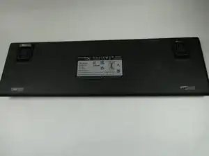
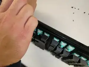
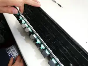
    • Remove all Philips #0 screws from the new openings created after removing the rubber feet and plastic tab.

  7. SnBo3KXiUNrLsLgt
    SnBo3KXiUNrLsLgt
    GGSThZJGrtZrKvMh
    TmDoGJuWJO3KHFLE
    • Separate the backplate from the keyboard using your hands.

  8. Z5AHMsCZ22qDhyHQ
    Z5AHMsCZ22qDhyHQ
    eH3WRaHUFwOLRCPa
    qCjNMxL35DeHNRD2
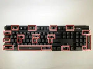
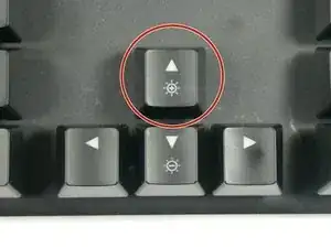
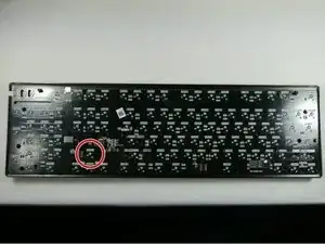
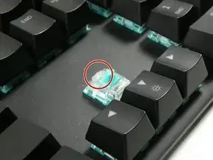
    • Identify the key switch to be replaced.

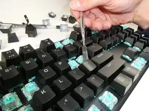
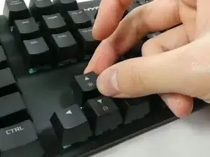
    • Remove its keycap by carefully prying it off of the keyboard with your fingers.

  9. EvwBr2jqOZhPg4Ug
    EvwBr2jqOZhPg4Ug
    HiDmw4mVKGsfyMpy
    • Flip the keyboard over to face the PCB.

    • Identify the corresponding switch to be removed.

  10. eJUZNmHDcfpNUdMA
    • Plug in and turn on your soldering iron.

    • Do not touch the metal end of the soldering iron while it is powered on. Allow the soldering iron to cool before stowing it away.

  11. U2kOgvCAMtlNkSQO
    U2kOgvCAMtlNkSQO
    j3CwbLVhO4FBACIR
    QynIagxAJ2oiUNpB
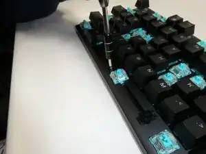
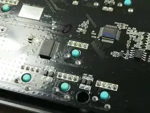
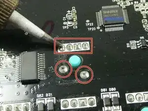
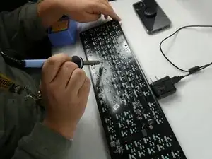
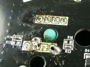
    • Melt the solder surrounding the four pins of the switch's LED, and the two lower pins of the switch body.

    • To remove the melted solder, use a desoldering iron, a desoldering pump, or desoldering braid.

    • The exposed switch pins are susceptible to damage from the soldering iron. Avoid applying heavy pressure to mitigate pin bending.

  12. aLIUTnR4SWxcDdnR
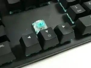
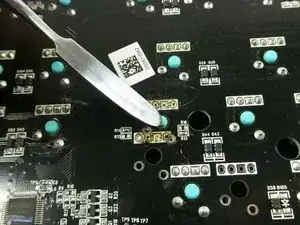
    • Using a spudger or another metallic instrument, firmly press down upon the exposed plastic of the switch. This will separate the switch from the rest of the keyboard.

    • If the switch's pins will not separate from the keyboard's PCB, continue applying the soldering iron to the pins to melt any residual solder.

  13. nYFDeKWGSwihdejl
    • Gently pull the LED off of the switch.

    • Do not break the LED pins while it is still attached to the switch.

Abschluss

To reassemble your device, follow these instructions in reverse order. Note that when reattaching the switch back to the keyboard PCB, the switch needs to be held in place behind the keyboard while soldering.

Adam Sles

Mitglied seit: 25/10/22

199 Reputation

0 Kommentare