Einleitung

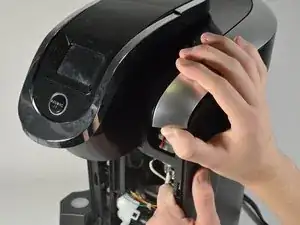
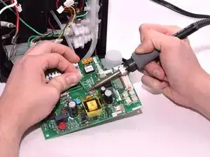
In this guide, you will replace the circuit board. This is necessary if the board is faulty, which could make your brewer dispense drinks incorrectly. You will need to know how to solder and desolder connections to completely remove the circuit board from the device.

  1. q5wZFxP642VIA5oZ
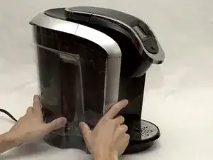
    • Locate and grab the Water Reservoir with your hands.

  2. kGcf1U1Sha4UBURi
    kGcf1U1Sha4UBURi
    qKVXuLtDUEdATaPR
    MxibAJC6iv1xZM4j
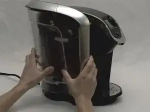
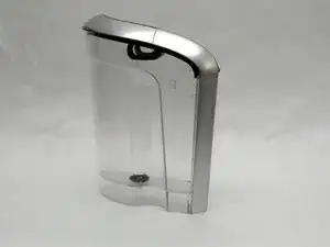
    • Lift the Water Reservoir up. It should be easy to separate it from the main part of the brewer.

  3. NJDmcHDpEMnxGlNT
    NJDmcHDpEMnxGlNT
    hu15lSAGID5EBiql
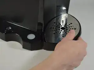
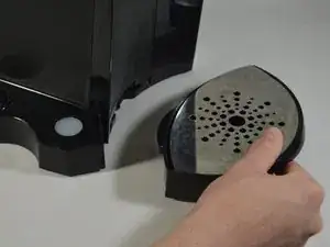
    • Remove the Drip Tray by pulling it out of the device.

    • This Drip Tray is the detachable bottom part of the Keurig machine where you place a cup or mug.

  4. uhrkrKb22SXuEJeF
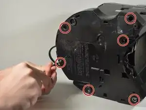
    • Using the Phillips #1 screwdriver, remove the six 140mm screws from the bottom of the Keurig machine.

    • If it is hard to unscrew using only the Phillips #1 screw head, insert the 60mm Shaft Extension into the back end of the screwdriver to help you.

  5. HSN2SShWD4QSNZ1L
    HSN2SShWD4QSNZ1L
    LveuJSBjXgOPi6tD
    xG4EDS1ITZwfICNT
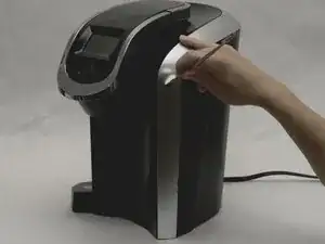
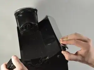
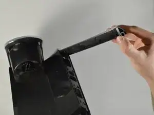
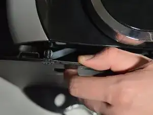
    • Use the metal spudger to separate the silver panel on the right side of the Keurig machine.

    • Tilt the brewer upside down and grab the bottom of the silver panel

    • Using your hands, peel off the silver panel from the Keurig machine.

  6. iGjM1qLEMMYfBuUf
    iGjM1qLEMMYfBuUf
    W2XenpSDcZVHEunP
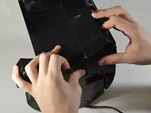
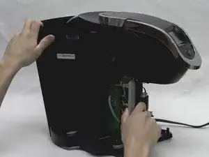
    • With one hand, place one finger inside the frame where the silver panel was attached and hold the base.

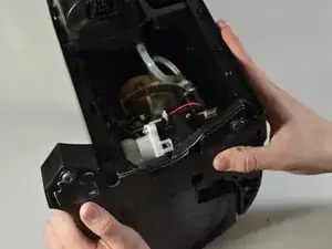
    • With the other hand, pull down to pop out the front housing of the Keurig machine.

    • You should now be able to see the components inside the Keurig machine.

  7. PN6HVsaFvRVZnSSy
    PN6HVsaFvRVZnSSy
    MT6ugNk3Qxol2UDX
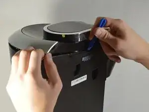
    • Using your hands, pry the back exterior of the brewer from the right side of the Keurig.

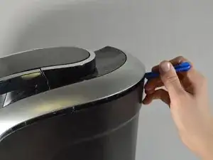
    • Use the blue opening tool to separate the top right silver panel from the back exterior.

  8. udWGGGqgYJioW1Rs
    udWGGGqgYJioW1Rs
    gq3Q6hRtcSiVYmm1
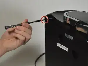
    • Use the Phillips #1 screwdriver to remove the 120mm screw located on the top left corner from the side of the brewer where the water reservoir was.

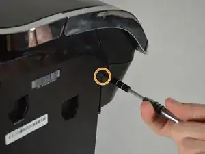
    • Use the Phillips #1 screwdriver to remove another 120mm screw located under the end of the empty slot running across the left side of the Keurig.

  9. qI1SuG1rIewwdLZf
    qI1SuG1rIewwdLZf
    iquMykUvX1nqFeGk
    • Separate the side panel from the top frame of the brewer, using the blue opening tool for help if necessary.

  10. Y6fZZN3nWM6YR6bm
    Y6fZZN3nWM6YR6bm
    YulYAOFMaqUgvSw6
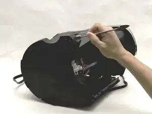
    • Place the brewer on its side as shown in the picture

    • Using the metal spudger, pry away the housing surrounding the sides of the Keurig machine from the bottom.

    • Work your way around the perimeter of the base.

  11. USdkx5jKilSxR1KO
    USdkx5jKilSxR1KO
    DoYOLosH5UwkL5hB
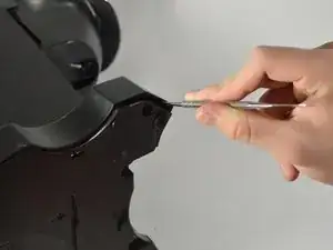
    • Remove the entire back exterior surrounding the Keurig by removing the latches connecting the back exterior to the silver frame on top. To do this, use the metal spudger to lift the latches up and out.

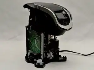
    • The inside of the Keurig should now be exposed.

    Why are steps 12 through 15 required? It doesn't seem like they are needed to perform the final step, as the sensor and connector on the opposite side are both accessible at this point.

    David Zeller -

  12. hJdYqDMgDBhjRUgt
    hJdYqDMgDBhjRUgt
    HXhdMDfTCYeU3Hh4
    FyG2XhpDNGhMqkfC
    • Reorient the brewer as shown in the picture.

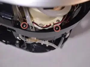
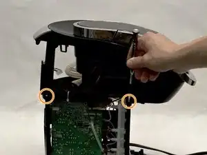
    • Locate the four 140mm screws holding the top frame of the Keurig in place. Remove these screws using the Phillips #1 screwdriver.

    • Two of the screws are on the inside of the frame close to the water heater.

    • You may need to decrease the size of the screwdriver in order for it to fit inside the frame. Do this by taking out the bit extender.

    • The other two screws are located on the outside of the frame.

  13. UsfDtqZBGGndIEYN
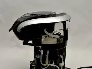
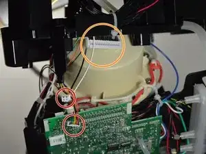
    • Remove the top of the framing that encases the circuit board.

    • Remove the wires that are connected to the top of the circuit board.

    • Pull out the multicolored wires by their bases.

    • The bundle with black wires and one red wire is connected to the very top of the circuit board. To remove these wires, squeeze in the white tabs as you pull them out.

  14. CXIFQFeSxVsdXT3b
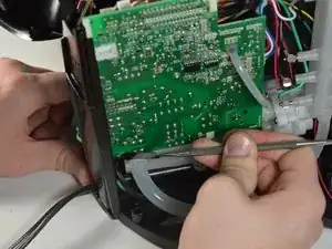
    • Using the metal spudger, snap the circuit board out of the latches on the bottom of the board.

  15. 3qmiYDGIqWohsZoM
    3qmiYDGIqWohsZoM
    kytBsASOu4voqWJt
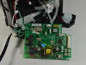
    • Unplug the rest of the wires connecting to the circuit board by pulling them out by their bases.

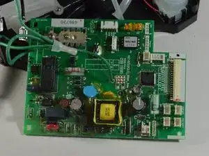
    • In order to free the circuit board completely, you have to desolder the connections that restrain it. Use our How to Solder and Desolder Connections Guide to properly and safely conduct this procedure.

    • Remove the circuit board from the device.

    Good day. What is the value/details of the MOV1 (metal-oxide varistor)? Thanks in advance.

    John Michael Ortiz -

    Also want to know this capacitor part number. My one burnt out…

    chai chaiqinglink -

    Excellent photos, especially of circuit board. Thanks! I am curious what manner of beast U1 is: FPGA, micro controller and/or any details. It’s been while since I worked on such control circuits and rarely mass-produced items so choices are different. BTW I cam here trying to troubleshoot why the clock is randomly reset, even in the absence of power failure. I can buy a cheap similar unit - not quite yet, at a thrift store if I wanted to replace the entire board.

    Joseph Ryan -

    The only things i know from the varistor : It’s from littelfuse and what’s printed on the varistor is LF9 P1505 1638 (on my K550 with a K543 MAIN BOARD) but no clue for real part number.

    Pascal Ste-Marie -

    I would love to get my hands on a circuit diagram for this board. What do VR1 and VR2 do? Is one of them a control for the sensitivity of the pressure switch FPN-15PG that shuts the system down if the pump pressure gets too high indicating a possible clogged dispenser pin? The VR would go between pins 1 and 6 and be about 200 ohms max.

    eagle49624 -

Abschluss

To reassemble your device, follow these instructions in reverse order.

Alec Jamosmos

Mitglied seit: 23/04/18

915 Reputation

5 Kommentare

Just curious what the phone jack on the bottom is for. There seems to be no mention of this in the user manual.

Joel Lautzenheiser -

Weird too that there is a UART mark on the circuit board. Is the coffee maker supposed to ‘phone home’ or obtain firmware updates? I think not.

Joseph Ryan -

is there a thermal fuse somewhere?

Chris Knudson -

or if it’s dead, the circuit board?
Chris Knudson -

I'm embarrassed to admit, I forgot which wire goes on which spade connector. :( I know for sure the red wire goes on the middle circuit board spade connector, but now I can't remember if the white wire goes on the top spade connector, or on the bottom corner. Does anyone have a photo of theirs or do you have a clear recollection of whether white is on the top or bottom spade?

Steve -