Einleitung

  1. M1YyHmJ6G2otd6lr
    M1YyHmJ6G2otd6lr
    5oRJDtPWflKHt5ui
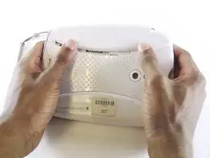
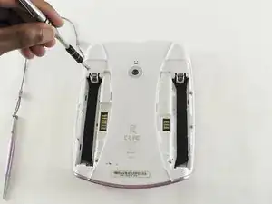
    • Turn the tablet so the back is visible.

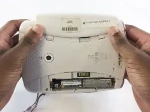
    • One at a time, remove the battery covers by sliding them towards the sides and away from the center of the device.

    I have changed batteries but it still don't turn on I press the power button it flashes white on screen but goes off please help

    kim30449 -

    The battery cover wont budge!

    Sunny Sky Official -

  2. LHxHfCU3oPhRSGbB
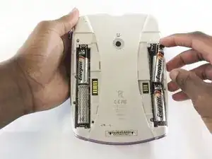
    • Remove the AA batteries from both battery compartments of the device.

    Where's the battery packs the batteries are supposed to be in ?.

    James F Crack -

    PeuTu on chAngers les piles par une batterie

    bernadette.honore -

  3. WUhh5VsMEEG2y4IU
    WUhh5VsMEEG2y4IU
    qMpmNYcp3ONUFAIS
    DA3IT2TbBDWWnsA2
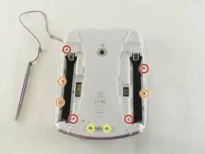
    • Use a Phillips #1 screwdriver to remove the following screws from the device:

    • Four 7.0mm Phillips screws

    • Three 6.0mm Phillips screws

    • Two 10.0mm Phillips screws

    • These two screws are behind the barcode decal on the bottom of the device. Expose the screws by puncturing, cutting, or peeling the barcode decal.

  4. BX4b3Jd6fJIMuEol
    BX4b3Jd6fJIMuEol
    UvQKVrVFqPf4m6cb
    1BRXPyHUNQC4CeLD
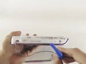
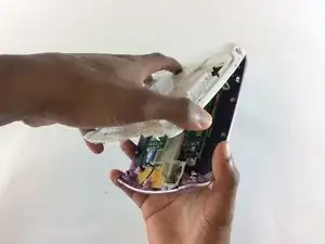
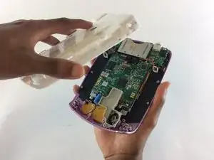
    • Use a small plastic opening tool to begin separating the colored front cover from the white rear cover of the device.

    • With one hand on the front cover and one hand on the rear cover, start from the bottom of the device and begin pulling the pieces apart.

    • The most stubborn tabs holding the front and rear together are along the top edge of the tablet around the game cartridge slot. This will most likely be the last area that separates, and it may require a moderate amount of force.

    • Once only the top edge remains connected, simultaneously pull the rear cover backwards away from the front cover and upwards towards the top of the device. This should release the last remaining tabs holding the pieces together.

  5. TUKXqYl4WadyMyvU
    TUKXqYl4WadyMyvU
    YVexbYajoWhVDrwk
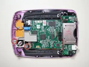
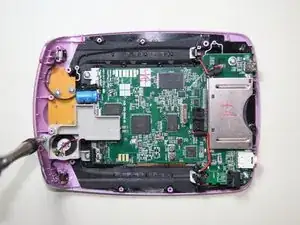
    • Use a Phillips #1 screwdriver to remove two 5.5mm screws from the plastic speaker holder.

    • The rear camera is shown removed in these images, but its removal is optional for most tasks.

  6. aKK3TgygHBLZE5qX
    aKK3TgygHBLZE5qX
    GKq5iXRcKlxs1XGx
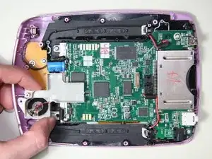
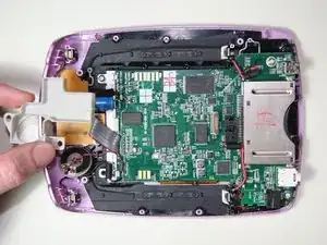
    • Remove the plastic speaker holder from the device.

  7. IaCFiUYnERM4twql
    IaCFiUYnERM4twql
    VAEHQxmkNMLArvZQ
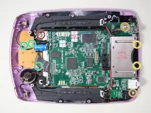
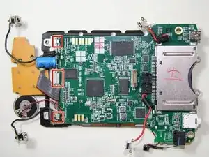
    • Use a Phillips #1 screwdriver to remove the following screws:

    • One 5.5mm Phillips screw holding the screen assembly.

    • Two 8.0mm Phillips screws holding the motherboard.

    • Two 6.0mm Phillips screws holding the game cartridge slot.

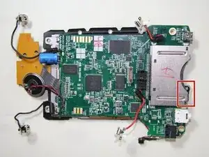
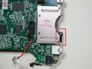
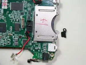
    • One of these screws also holds a black plastic bracket for the front camera, and the bracket is loose once the screw is removed. Set the bracket aside if it falls out.

    • Remember to replace the bracket during this step of reassembly if it was removed.

    • Three 6.0mm Phillips screws holding the auxiliary board.

    • Be careful not to damage the gray ribbon cable connecting the auxiliary board when removing these three screws.

  8. DCNvfhuhREeDbp3q
    DCNvfhuhREeDbp3q
    i3JQjyh5UHEhM23t
    Vi5m4cZxOcZvxXsM
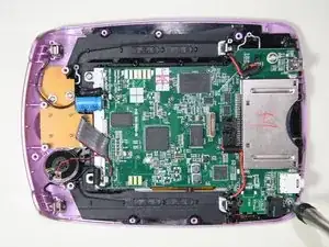
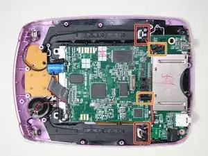
    • Locate the following:

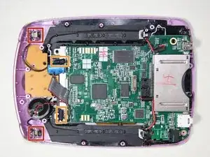
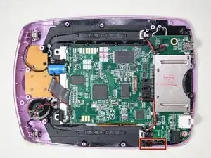
    • Two positive battery terminals.

    • Two positive battery wire glue-points.

    • This glue may separate from the motherboard while detaching the battery terminals, but this has no significant impact on the device.

    • Gluing any separated wires back to the motherboard is an optional reassembly step.

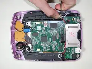
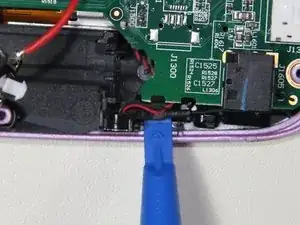
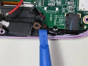
    • One terminal at a time, insert a narrow metal spudger through the metal loop of each terminal from the side and pry upwards away from the front cover to release the terminal from the cover.

    • A metal spudger is used because it requires significant force to release the positive battery terminals.

  9. YSDY1LpQQIPNbhe6
    YSDY1LpQQIPNbhe6
    dsEIcGf15UxGymtA
    CYoI4cucYNFQjwUk
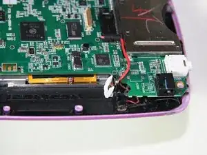
    • Locate the following:

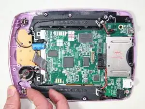
    • Two negative battery terminals.

    • Two negative battery wire glue-points.

    • This glue may separate from the motherboard while detaching the battery terminals, but this has no significant impact on the device.

    • Gluing any separated wires back to the motherboard is an optional reassembly step.

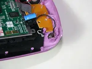
    • One terminal at a time, pinch the battery side of the terminal towards the wire side of the terminal with a finger or thumb, and pull upwards away from the front cover to release the terminal from the cover.

    • The negative battery terminals require much less force to remove than the positive battery terminals.

  10. 5yNrW6WuiGlERWjc
    5yNrW6WuiGlERWjc
    niSuREXdMIOfKqSc
    qmwuldBFUWSmkxJ2
    • Use the small plastic opening tool to gently lift under the side microphone's black wire to remove the microphone from its slot.

  11. 6AmNXiKcMgPjvwC4
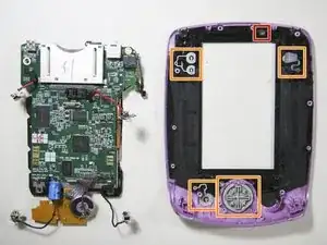
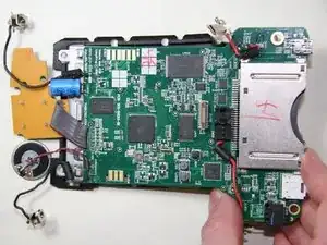
    • Holding the front cover with one hand and the sides of the motherboard with the other, lift the motherboard away from the front cover.

    • The following may become loose and fall out of position. Reposition them if necessary.

    • Front camera lens.

    • Buttons.

  12. URD3NLYTQxSOwIDR
    URD3NLYTQxSOwIDR
    SdIeTKdnsZnCodf3
    556hDqsGlNvS2Xsn
    • If the bracket did not previously fall out after removal of the game cartridge slot screws, remove it now and set it aside for reassembly.

    • Front camera bracket location.

  13. EIEILLFefLPaTQZi
    EIEILLFefLPaTQZi
    GRKJKtrMTZlElFPZ
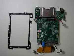
    • The rubber screen border may separate on its own after removing the front cover from the screen assembly and motherboard. Set it aside if it comes off.

    • Pay attention to the original orientation of the rubber screen border to facilitate reassembly.

  14. jcs5TcXsgvqRB5rl
    jcs5TcXsgvqRB5rl
    d31JSmiHejWPDgYJ
    • Screen assembly tab locations.

    • Slide the motherboard in the direction of the game cartridge slot until the motherboard is out from under the metal tabs on the screen assembly.

  15. 1iNTpnCMtwDCPXHv
    1iNTpnCMtwDCPXHv
    THfJxg1uxI4bkJT1
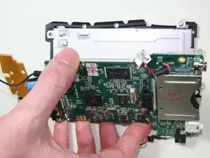
    • Carefully flip the motherboard over by pivoting away from the screen assembly along the long edge with the microphone and speaker, as shown.

    • The motherboard and screen assembly are still connected by a ribbon cable that can be damaged if stressed severely.

  16. np4usM6a46hq2LF2
    np4usM6a46hq2LF2
    g2WYAYmKA25yaAB1
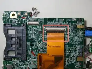
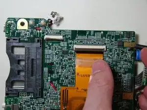
    • Peel back the tape on the display ribbon cable connector.

    • The front camera is shown removed in these images, but its removal is optional for most tasks.

  17. kUSRryOJJ6WJh2FE
    kUSRryOJJ6WJh2FE
    bPXrCalEdkduWJOV
    vuQHYcE4kisUj6LK
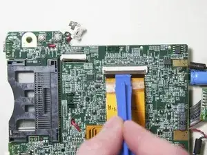
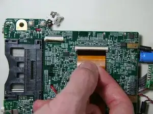
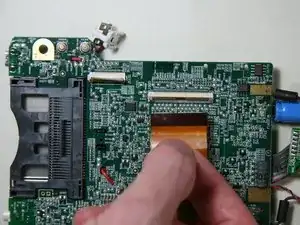
    • Open the display connector by lifting on the brown latch with a plastic opening tool or a finger until it is in a vertical position.

    • Failing to do this correctly could result in damage to the cable and/or connector.

    • Gently pull on the display ribbon cable and it should easily slide out of the connecter.

    • If the connector is properly open, disconnecting the ribbon cable should require little to no force.

  18. D4XKiYNLZKfNyfHy
    D4XKiYNLZKfNyfHy
    pHRsYtUr6TrmruxF
    ZfnjhK6NjBbknMKG
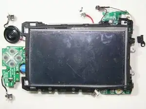
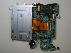
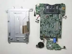
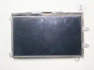
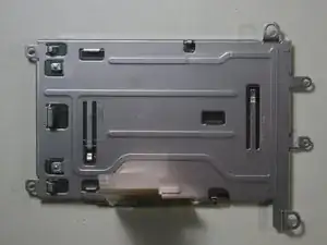
    • The screen assembly is now separated.

  19. ZKTUVViUmZesStm4
    ZKTUVViUmZesStm4
    KVoKZTNFndGfnXXG
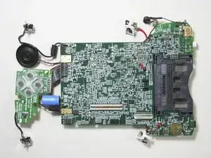
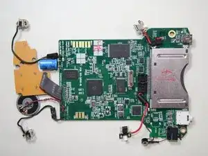
    • The motherboard is now separated.

  20. CZLDORLA4ZN4UZrK
    CZLDORLA4ZN4UZrK
    1UDXS2VhkBkIMgQo
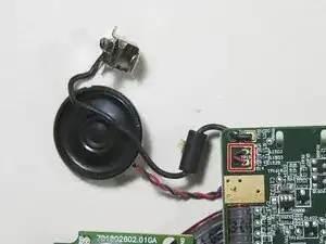
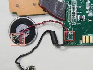
    • Speaker wire terminal locations.

    • Desolder the speaker wire connections at one of the two terminal locations shown.

    • For proper soldering and desoldering techniques reference Wie man Lötverbindungen herstellt und entlötet.

    • Soldering requires the iron to be at hot temperatures and can cause burns. Wear safety glasses as needed.

    • Be extremely careful with the cables in this step as they could melt, burn, or break.

Abschluss

To reassemble your device, follow these instructions in reverse order.
Chase Mamatey

Mitglied seit: 05/10/16

326 Reputation

0 Kommentare