Einleitung

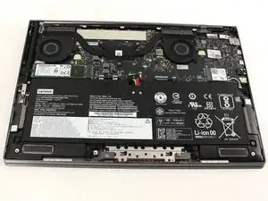
This guide includes all the steps, tools, and parts necessary to disassemble the Lenovo Yoga C930-13IKB to access and replace the hinge assembly.

  1. PGwdSeNHuIIRRAXY
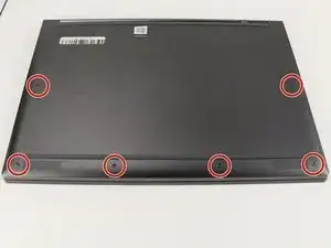
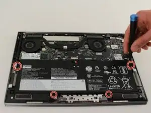
    • Flip the device over so that the underside is facing up.

    • Remove the six 3.5 mm T5 Torx screws.

  2. FiWHDiuuINDJFtQr
    FiWHDiuuINDJFtQr
    t5ZLbWjWV6hmBpOI
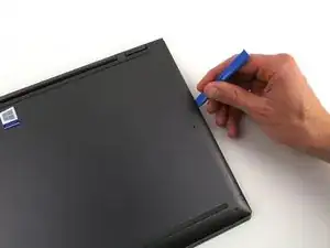
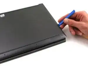
    • Pry off the back cover using the plastic opening tool.

    • Loosen the back cover in multiple spots using the opening tool, then remove the whole back.

    • You may have to run the plastic tool along the edges until you find a small gap to separate the back cover from the laptop.

    • Do not use a metal tool when working with your device.

    The gap is so small that I wasn’t able to insert anything to pry the cover up. The suction cup tool lifted the cover off easily.

    Thomas Capobianco -

    There is a very convenient spot to begin the prying process. Up by the hinge, where the metal back turns in perpendicular to the edge to get around the hinge mechanism, there is a gap between the cover and the rest of the laptop where it can be pried up easily. From there it is easy to run a tool and widen the gap all the way around.

    Alex Yantis -

  3. DeoIJJRpX2hNONcY
    DeoIJJRpX2hNONcY
    k1uvqt3b2ScVvJ5s
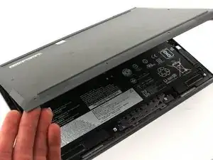
    • Carefully lift the cover off with your hands.

  4. 2FISN3TQKpsRcePJ
    2FISN3TQKpsRcePJ
    bh26yNV5wwwpRZOk
    642aakhV2bHDgExw
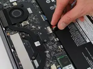
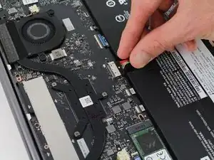
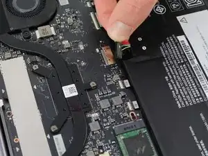
    • Unplug the battery from the motherboard by pinching the cables with your fingers and tugging out with force.

    • Use the spudger for assistance.

    Pull cables toward yourself.

    Delphine Jacquet -

    I was not able to grasp the wires with the battery mounted. Once I removed the battery from the case, the connector was easy to remove

    Thomas Capobianco -

  5. QCvoFCpoH5HXqOPU
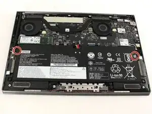
    • Unscrew the four 3mm screws with a Phillips screwdriver.

    I used a PH000 for this

    Matt Orienter -

  6. bNLnHfbRxsCJbsCk
    bNLnHfbRxsCJbsCk
    WJNbDD4VLA3Qt5qW
    • The battery is still held in place with two stretch-release adhesive strips, similar to ones found in an iPhone.

    • Use your fingers to pry up the clear plastic pull-tab for one of the stretch release adhesives.

    • Grasp the pull-tab and slowly pull away from the battery at a shallow angle. The adhesive strip will stretch to many times its length and slowly release from underneath the battery.

    • Repeat the procedure for the second strip on the opposite side of the battery.

    • Be careful not to bend the battery. Breaking the battery is dangerous.

    • Remove the battery with your hands.

    There are two clear plastic tabs wrapped around the sides of the battery that connect to the glue strips between the battery and the backlight cover. All you have to do is peel the clear strips from the battery and pull them away. The glue under the battery pulls out like a Command Strip. No need to wreck your backlit cover and possibly the cabling underneath with tools.

    Brian Storm -

    Oh man I really wish I would have expanded the comments before continuing; something that took me an hour of painstaking prying could have been taken care of in 30 seconds. USE THE PULL TABS TO REMOVE THE ADHESIVE STRIPS!

    Ben Borgert -

    Hi Brian,

    Thanks for the tips! I’ll amend the guide to include this info.

    Arthur Shi -

    I still don’t understand Step 6. Also does the new battery stick to the existing adhesive strip?

    Allen Michael Cohen -

    @BenBorgert - agree 100%!! I would also add that I had to give the cover a nudge towards the hinge (something seemed to click into place) to get the screw holes lined up

    Thomas Capobianco -

  7. lcNmOYdUq6TFshRg
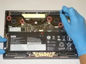
    • Remove the four 3 mm Phillips #0 screws from the fan assembly.

  8. ScWZFEnjUnQc2xDO
    • Remove the four 2 mm Phillips #00 screws from the fans themselves.

    This is another redundant step since this is only to secure the fans to the heat pipe fan housing. And really tiny screws to lose.

    imark7777777 -

  9. uCZR3DdZcZluXG4k
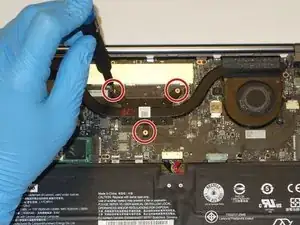
    • Unscrew the three 3 mm Phillips #0 screws on the heatsink.

  10. PVGxMbC1sUlJOVZf
    PVGxMbC1sUlJOVZf
    LmVYJpNNW2QSMTpQ
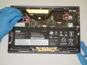
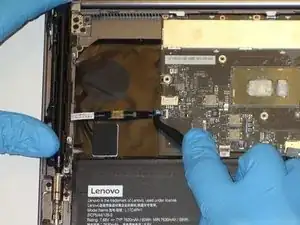
    • Use a plastic opening tool to remove the two small, white power cable connectors for each of the two fans.

  11. sG5QmxjigWFMZZXe
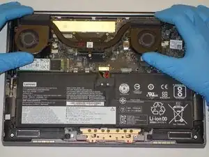
    • Gently lift the fan assembly out of the laptop.

    • Be sure to clean and reapply thermal paste to the heatsink during reassembly.

  12. LNfSuob5PS5ZvWff
    LNfSuob5PS5ZvWff
    D5NprS6SKySjqUhU
    sPWJVVCPK1IGGNDD
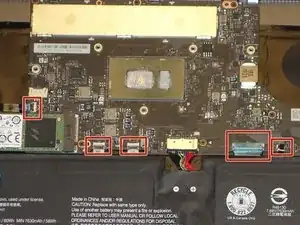
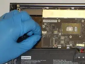
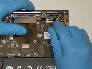
    • Using the Halberd Spudger, gently lift the black tab on top of each of the five ZIF connectors for the ribbon cables. Then pull the cables out from the connectors.

  13. MJPIQqY2rx2lshYw
    MJPIQqY2rx2lshYw
    tk6VLX1Y4QjGNm6p
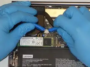
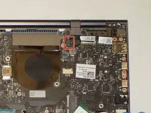
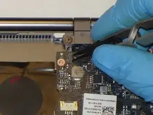
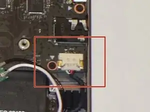
    • Using the reverse tweezers, gently pull out the small black cable towards the top right of the motherboard.

  14. iYl2PTEennxOe5CH
    iYl2PTEennxOe5CH
    VNYIRJEEpvCSQKV2
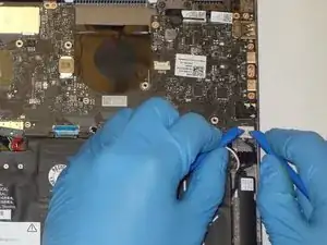
    • Using two plastic opening tools gently unplug the white speaker cable connector from the bottom left of the motherboard.

  15. MbKL2NEPLEkGjwxM
    MbKL2NEPLEkGjwxM
    DBENl4t6HqQEEEXK
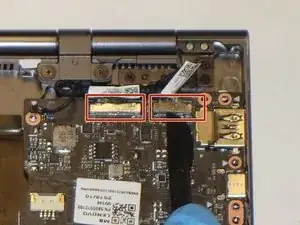
    • Using the plastic opening tool, gently pry up on the metal tabs of the two display cables to remove the cables from the top right corner of the motherboard.

  16. 4T22OUquPToNYCQh
    4T22OUquPToNYCQh
    2NuYysr1TWJ33VF2
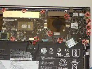
    • Remove the fourteen 3 mm Phillips #00 screws that hold in the motherboard.

  17. 5OeVmVkcSBwyKinQ
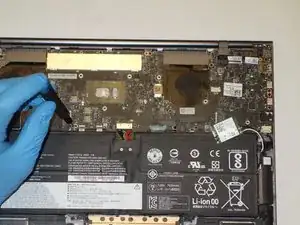
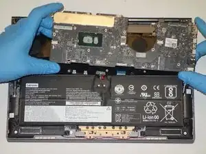
    • While gently grasping each side of the motherboard, carefully lift the assembly out.

  18. oNJtsja5YlMSp6NA
    oNJtsja5YlMSp6NA
    cDbchhXjYIWS43SS
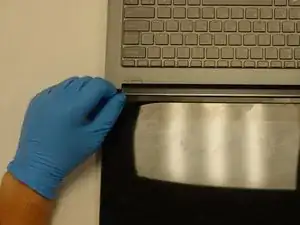
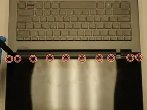
    • Using a halberd spudger, gently lift up the metal bezel that lines the lower edge of the display.

  19. QDQsW5vBlFyyA2fE
    • Remove the ten 3 mm screws along the bottom edge of the display with a Phillips #00 screwdriver.

  20. SiyhBRyZ1wNKI5rX
    SiyhBRyZ1wNKI5rX
    qqWRedPwGXODtUhc
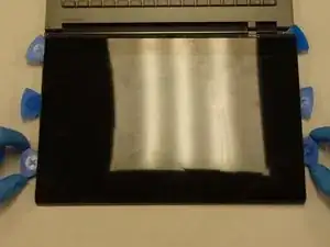
    • Gently wedge two opening picks underneath the display.

    • Slowly work the opening picks around the display.

    • Add opening picks as needed to keep display separated from the frame.

    • Use caution if dealing with broken glass.

    • The iFixit suction cup tool can be used to add some extra leverage to the mix when removing the display.

  21. 4IumNUcZQwWiurV3
    4IumNUcZQwWiurV3
    JLcIAEsVsBULZw3T
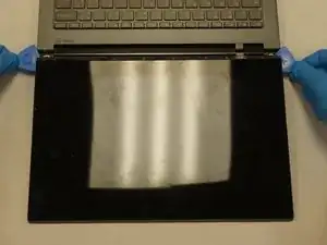
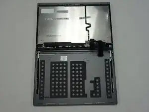
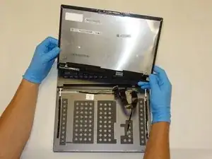
    • Gently flip the display assembly to rest on top of the keyboard.

  22. EVYw2AvRj5Qv4T24
    EVYw2AvRj5Qv4T24
    xFwEZaKwieIwbHvt
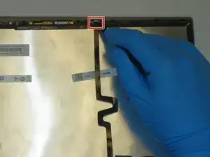
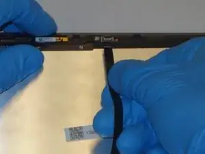
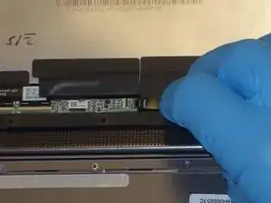
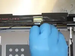
    • Use the halberd spudger to lift the locking tab of the ZIF connector holding the black ribbon cable that runs vertically across the display.

    • Pull out the black ribbon cable from the connector.

  23. IcXDX6uLpJZ6YwYo
    IcXDX6uLpJZ6YwYo
    paAhbpVvVTI1nP1b
    DOTFZwAh3laqP4wm
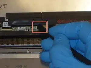
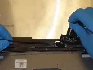
    • Use the halberd spudger to lift the latch on the ZIF connector of the horizontal black ribbon cable.

    • Pull out the horizontal black ribbon cable from the connector.

    • Gently pull the rest of the horizontal black ribbon cable from the back of the display.

  24. RJjiBTkHWbJ44gRW
    RJjiBTkHWbJ44gRW
    ALEoUuGKHARFINCR
    axmi1NMXBvhMxL3G
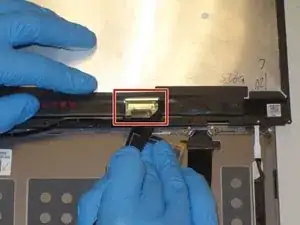
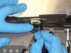
    • Use the halberd spudger to flip the metal latch of the display cable up.

    • Using the halberd spudger, gently pull the connector out of the display.

  25. SU2pvATdqLhoY3nl
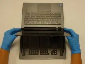
    • Gently lift the display away from the laptop frame.

  26. JBiWPxSOeShKYip5
    JBiWPxSOeShKYip5
    6dTM3yWkXkageKJN
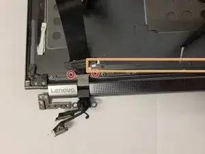
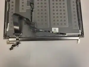
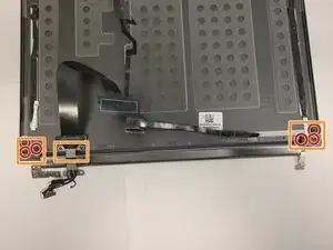
    • Remove the eight 3 mm screws from the hinge attachments on the back cover using the Phillips #00 screwdriver.

    • Carefully detach the hinge assembly connectors from the LCD cover to detach it from the back cover.

  27. uQNfv1HP42qYIYw5
    uQNfv1HP42qYIYw5
    lEMSdlVMWgaXUpoF
    X22yFgievQFDMtoH
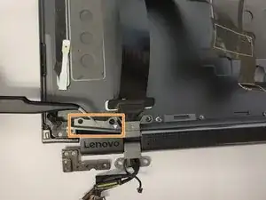
    • Using a Phillips #00 screwdriver, remove the two 3 mm screws from the hinge attachment on the LCD cover.

    • Detach the two hinge retention brackets using the angled ESD tweezers.

  28. NkHcO1s6jcRw4I2K
    NkHcO1s6jcRw4I2K
    DGPshya3rknnAjBF
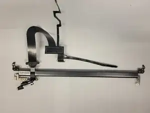
    • Using a Phillips #00 screwdriver remove the six 3 mm screws from the corners of the LCD cover.

    • Carefully lift the hinge assembly, detaching it from the LCD cover.

Abschluss

To reassemble your device, follow these instructions in reverse order.
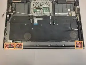
Elizabeth Miller

Mitglied seit: 20/09/21

208 Reputation

0 Kommentare