Einleitung

  1. FuPn2jOvDowMLfXU
    FuPn2jOvDowMLfXU
    CM1DXhgLeVUrEvbB
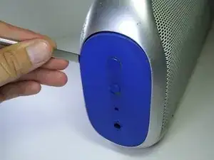
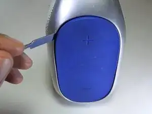
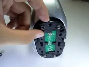
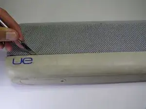
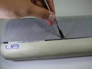
    • Use a metal spudger to pry open the power button cover.

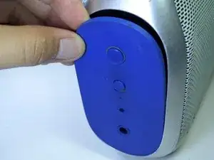
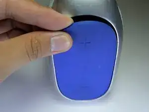
    • Once the power button cover is slightly opened, use your fingers to remove the power button cover.

  2. NstHqbWuxOZBfhIV
    NstHqbWuxOZBfhIV
    1ZFWYPJrPCfPMn4Q
    ovX3XZoOXvfGnGAl
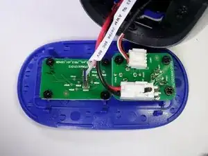
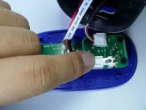
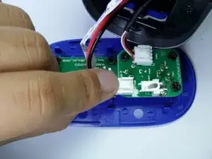
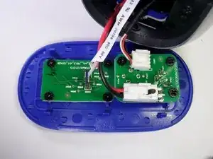
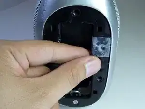
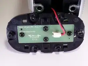
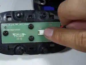
    • Press firmly on the end of the latch and pull the two-wire connector away from the base to separate.

  3. Y2TEfv6GxhrGjC1O
    Y2TEfv6GxhrGjC1O
    bsTsK5WFkfQNmgEk
    slOpb5Z6saihBc1c
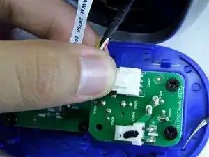
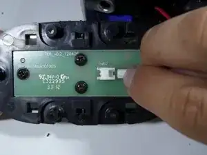
    • Firmly press on the end of the latch and pull the four-wire connector away from the base to separate.

  4. kYdiEZs3bZwywFdL
    kYdiEZs3bZwywFdL
    RJ5QfV1SHXa3sFLE
    oSeWVJpaGwAaxxUa
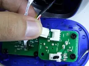
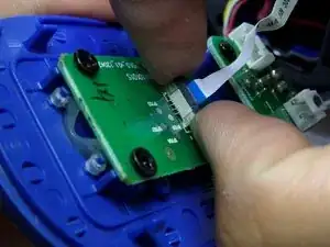
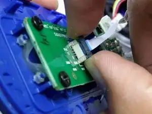
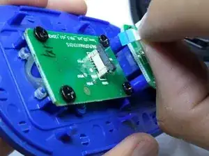
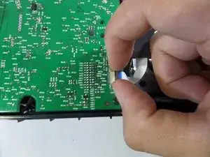
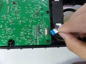
    • Lightly, pry up on each side of the black band connector lock using your fingertips.

    • Once unlocked, pull straight up on the connector to remove.

  5. 2VlesWuRFXyQSGWG
    2VlesWuRFXyQSGWG
    LPxsbubUvJLfqOFD
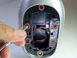
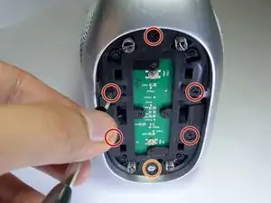
    • Remove the five black 14mm Phillips #2 screws from the black plastic side panel.

    • Remove the one silver 16mm Phillips #2 screws from the black plastic side panel.

    • Remove the black plastic screw panel from the boombox.

  6. oNmvJFGqqXgdPttW
    oNmvJFGqqXgdPttW
    I2qVXuBSoDvtov1G
    • On the opposite side of the device, pry open the volume rocker with a metal spudger.

    • Remove the panel with your fingers once the volume rocker is slightly opened.

  7. HUa4ofDSJ6Wu5qm3
    HUa4ofDSJ6Wu5qm3
    ReF6gWShDJEWYXyy
    2fTciLFWn3dxmJPd
    • Remove the five black 14mm Phillips #2 screws from the black plastic side panel.

    • Remove the one silver16 mm Phillips #2 screw from the black plastic side panel.

    • Once all screws are removed, take the screw panel out of the device to gain access to the back of the panel.

  8. OTbggVXpw5JuPVum
    OTbggVXpw5JuPVum
    HYFMJZDGWBj1KSOn
    • Firmly press on the end of the latch and pull the two-wire connector away from the base.

  9. nATZEtoaGXyWxYaS
    nATZEtoaGXyWxYaS
    vlHg3N1FWyVcBC6b
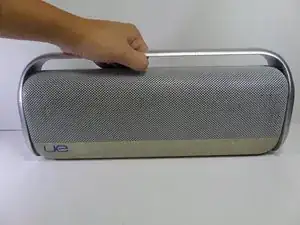
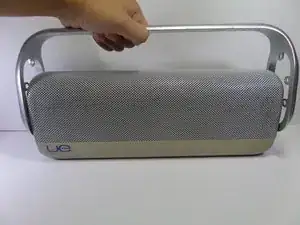
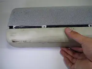
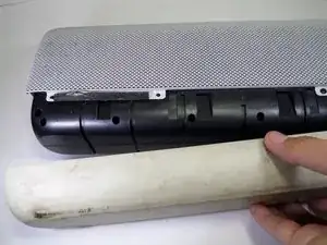
    • Pull up on the aluminum boombox handle to remove.

  10. URCwUC6ZDmkfqIBq
    URCwUC6ZDmkfqIBq
    ZyEgMKRRFeVrPniu
    • Use a metal spudger to pry the rubber base apart from the aluminum grille.

  11. Z4NFkMQVLUI2EuXO
    Z4NFkMQVLUI2EuXO
    BPNhKIOdKLIFYZwA
    • Pull the rubber base away from the boombox.

  12. GXTApfAQwDXCjvEH
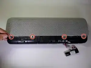
    • Remove the four black 7.5mm Phillips #2 screws on each side of the device.

    • There should be a total of eight screws removed in this step.

  13. 1uFyDlXasvieIodg
    1uFyDlXasvieIodg
    l5HrcL5qXNRkokmZ
    2ZbNSkWsgVApmGjH
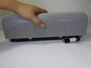
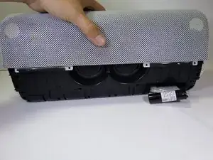
    • Pull vertically on the speaker grille to remove it from the boombox.

  14. ekPKCVWEdBuadXIa
    ekPKCVWEdBuadXIa
    sPk1PcpFrCfG6TrL
    fqdUBANy4hI4YNMM
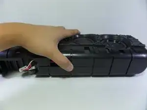
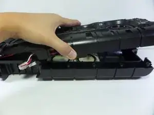
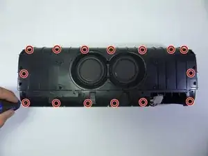
    • Remove the fifteen 13.0 mm screws with a #0 Phillips from the side of the device containing two speakers.

    • Separate the two halves by gently pulling them apart.

    • The screws at this step are embedded deep within the device so make sure your screw driver is long.

  15. mQysQiKJLq2GYHV5
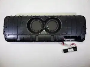
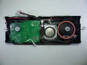
    • Locate the speaker adjacent to the motherboard.

  16. yHVKogEZFKsFXwjc
    yHVKogEZFKsFXwjc
    QQIPm3BReilcgIjs
    4mq2WuW5mhC5QtYK
  17. 5ZCGXHQ6THNZWe2X
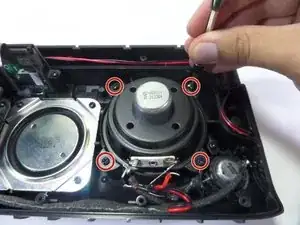
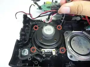
    • Remove the four 7.0 mm screws with a Phillips #2.

  18. rRCSq5ZN4XeeYSUO
    rRCSq5ZN4XeeYSUO
    vASag5tG45pddBhe
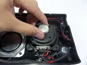
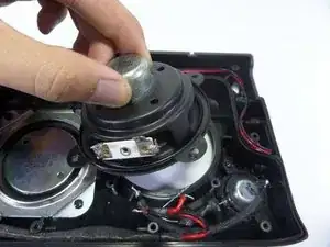
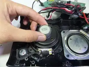
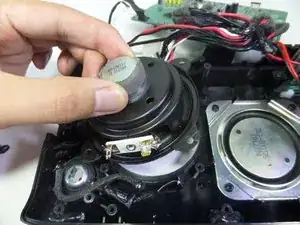
    • Lift the speaker out of the device using your fingers.

  19. Ywkjuje3Epv56RSO
    Ywkjuje3Epv56RSO
    t55CFoOiEGhgIRCb
    4pJAipBJfWx2OGIq
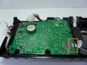
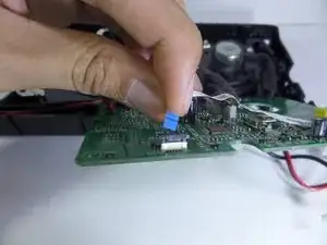
    • Pull up on the lock to detach the band connector from the motherboard.

  20. wldDYGpZtwX1mlWP
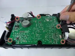
    • Remove five 7.0 mm screws on the motherboard with a Phillips #2.

  21. DIHAwFmtTWFeQVb3
    DIHAwFmtTWFeQVb3
    uL3oQWOTIrPoNA21
    JGTgJKqLYChcKBGy
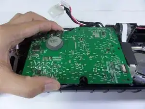
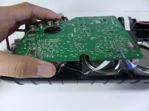
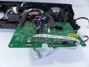
    • Lift the motherboard with your fingers.

    • Flip over to reveal the underside.

    • Motherboard will still be attached to the device.

  22. UljdQmkJousY3kVQ
    UljdQmkJousY3kVQ
    2NZ2qaeOZgVpqxZO
    D1ki2JDbuxnaes2k
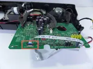
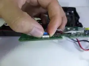
    • Pull up on the lock of the band connector to detach it from the motherboard.

  23. iusVtMKTYBHdfdpC
    iusVtMKTYBHdfdpC
    iL5YCFvoTlduJnBF
    KPBatosKjowGLVop
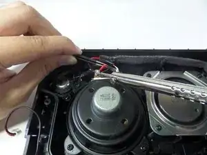
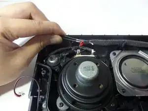
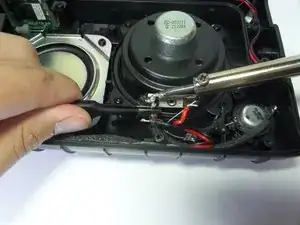
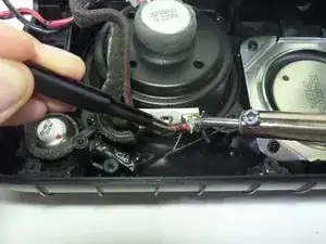
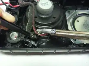
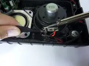
    • Desolder all four wires connecting the speaker.

    • One red and one black wire are located on each side of speaker.

  24. jsE3HTJU2WsNxcGr
    • Remove four 7.0 mm screws with a Phillips #2.

  25. ysIIOcUZfgmKCUWU
    ysIIOcUZfgmKCUWU
    olZCqTVvYOJNKxdE
    • Lift the speaker out of the device using your fingers.

    Sehr hilfreich, diese Reparaturanleitung!

    Klaus Fischer -

Abschluss

To reassemble your device, follow these instructions in reverse order.

Breean Mokede

Mitglied seit: 15/09/16

282 Reputation

Ein Kommentar

Could you recommend anywhere to find the correct replacement tweeters & drivers?
Ted Glasgow -