Einleitung
Grundständige Anleitung. Ausbau des Logic Boards und angeschlossener Komponenten.
Werkzeuge
-
-
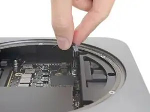
Fasse das Kabel der Stromversorgung und hebe es hoch, um es vom Logic Board zu trennen. Wackle unter Umständen ein wenig daran, um es abzulösen.
-
-
-
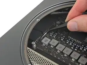
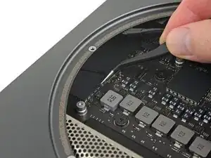
Hebe vorsichtig den Stecker der Status-LED gerade hoch und löse ihn aus seinem Anschluss auf dem Logic Board.
-
-
-
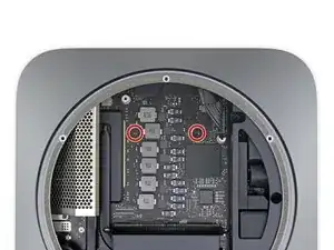
Drehe die beiden 7,5 mm Torx T10 Schrauben heraus, mit denen das Logic Board befestigt ist.
-
-
-
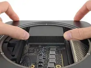
Setze die Daumen an jedem Ende des Abluftkanals über den Schraubenlöchern des Lüfters an.
-
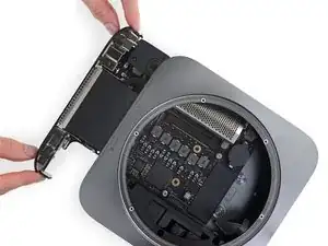
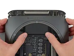
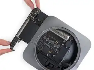
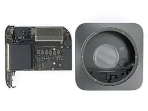
Drücke fest in Richtung der Anschlüsse, bis sich das Logic Board löst und das Logic Board aus dem Gehäuse herausgleitet.
-
Abschluss
Um dein Gerät wieder zusammenbauen, folge den Schritten in umgekehrter Reihenfolge


Loosen the side nearest outer case first
dermoid777 -
Is that a standard 20 pin power connector?
gotjoshua -
It appears there are curved metal tabs (1 on each side of the connector) that compress until they lock the connector in place or the connector is removed, but doing so evenly as to not break off the 2 gold knife blades on the logic board that slide into the plastic connector. Both the tabs & gold knife connectors are seen in the 2nd picture, in the first picture you can see how the tabs look when they are locked into the logic board connection.
bbbb -