Einleitung
Hier wird der Austausch des oberen Gehäuses gezeigt. Das obere Gehäuse enthält die Tastatur und das Trackpad.
Werkzeuge
Ersatzteile
-
-
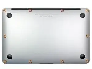
Entferne folgende Schrauben:
-
Zwei 8mm 5-point Pentalobe Schrauben
-
Acht 2,5 mm 5-point Pentalobe Schrauben
-
-
-
Zwänge deine Finger zwischen Display und Gehäuseunterteil und ziehe nach oben, damit es sich vom Air löst.
-
-
-
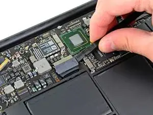
Hebele mit dem flachen Ende eines Spudgers die beiden kurzen Seiten des Akkusteckers nach oben, um ihn von seinem Anschluss auf dem Logic Board zu lösen.
-
Biege das Akkukabel etwas weg vom Logic Board, so dass sich der Stecker nicht wieder versehentlich mit dem Anschluss verbinden kann.
-
-
-
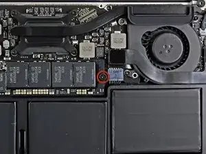
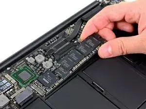
Hebe die SSD vorsichtig an dem freien Ende mit dem Spudger hoch, und zwar gerade nur soweit, dass du sie mit der anderen Hand fassen kannst.
-
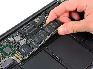
Ziehe das Laufwerk aus seinem Anschluss und entferne es vom Logic Board.
-
-
-
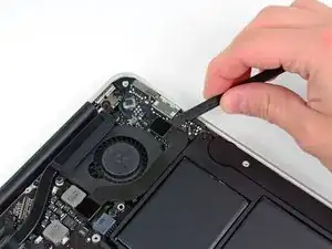
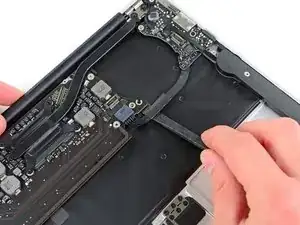
Heble den Stecker des I/O Board Kabels mit einem Spudger aus seinem Anschluss auf dem I/O Board.
-
-
-
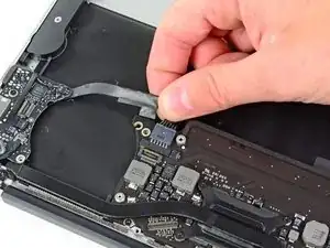
Löse das I/O Board Kabel vorsichtig von dem Kleber ab, mit dem es am Lüfter festgeklebt ist.
-
-
-
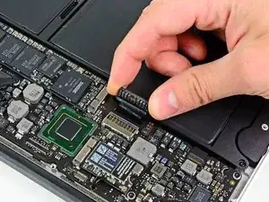
Hebe den I/O Board Stecker mit dem flachen Ende des Spudgers hoch und aus seinem Anschluss auf dem Logic Board.
-
Entferne das I/O Board Kabel.
-
-
-
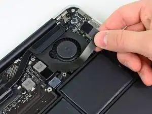
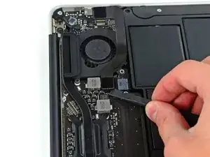
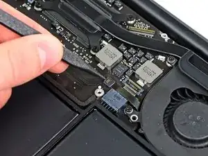
Klappe mit der Spudgerspitze vorsichtig den Sicherungsbügel am ZIF-Anschluss des Lüfterkabels hoch.
-
-
-
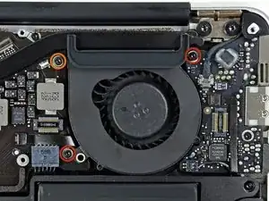
Entferne folgende drei Torx T5 Schrauben, welche den Lüfter am oberen Gehäuse befestigen:
-
Zwei 5,2 mm Schrauben
-
Eine 3,6 mm Schraube
-
-
-
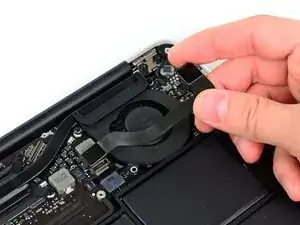
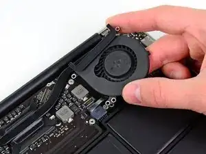
Hebe den Lüfter aus dem oberen Gehäuse und ziehe vorsichtig das Flachbandkabel zum Lüfter aus seinem Anschluss, während du ihn aus dem Air entfernst.
-
-
-
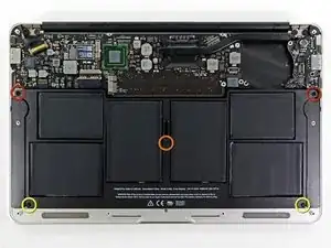
Entferne folgende fünf Torx T5 Schrauben, die den Akku am oberen Gehäuse befestigen:
-
Zwei 5,2 mm Schrauben
-
Eine 6 mm Schraube
-
Zwei 2,6 mm Schrauben
-
-
-
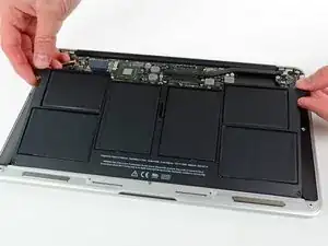
Hebe den Akku an der Kante an, die dem Logic Board am nächsten ist, und entferne ihn aus dem Gehäuse.
-
-
-
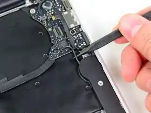
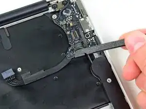
Das Versorgungskabel der I/O Karte ist mit einer Schleife aus Klebeband am oberen Gehäuse befstigt. Löse sie mit dem flachen Ende des Spudgers.
-
Trenne das I/O Board ab, indem du seinen Stecker aus dem Anschluss auf dem Logic Board ziehst.
-
-
-
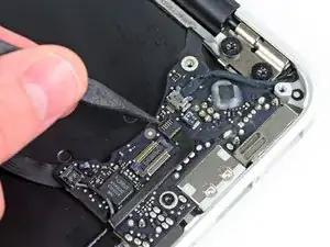
Klappe den Sicherungsbügel am ZIF Anschluss des Flachbandkabels der Tastaturbeleuchtung mit der Spudgerspitze hoch.
-
Ziehe das Flachbandkabel der Tastaturbeleuchtung aus seinem Anschluss heraus.
-
-
-
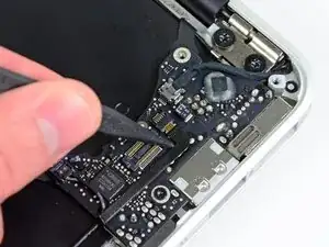
Klappe den Sicherungsbügel am ZIF Anschluss des Flachbandkabels zum Trackpad mit der Spudgerspitze oder deinem Fingernagel hoch.
-
Ziehe das Flachbandkabel zum Trackpad gerade aus seinem Anschluss in Richtung der Vorderkante des Air.
-
-
-
Hole das rechte Lautsprecherkabel mit der Spudgerspitze aus dem Ausschnitt im Logic Board.
-
-
-
Hebele den Stecker am rechten Lautsprecherkabel mit dem flachen Ende des Spudgers hoch und aus seinem Anschluss auf dem Logic Board.
-
-
-
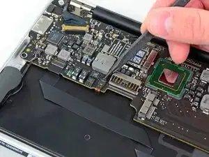
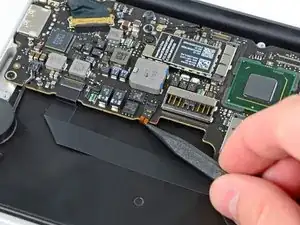
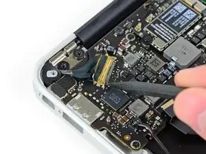
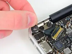
Schiebe vorsichtig einen Spudger unter die schwarze Plastikklappe, die am Sicherungsbügel des Displaydatenkabels befestigt ist, und lasse sie nach oben aufklappen, weg vom Anschluss.
-
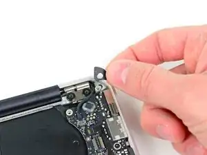
Entferne die kleine Gummidichtung in der Ecke des oberen Gehäuses nahe dem Displaydatenkabel.
-
-
-
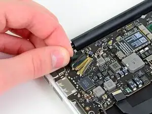
Halte den Sicherungsbügel weg vom Anschluss und ziehe vorsichtig das Displaydatenkabel aus seinem Anschluss heraus.
-
-
-
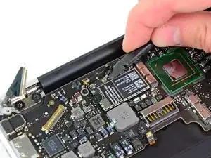
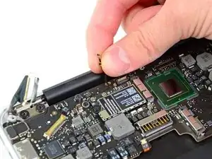
Heble beide Antennenstecker mit dem flachen Ende des Spudgers aus ihren Anschlüssen auf der AirPort/Bluetooth Karte hoch.
-
-
-
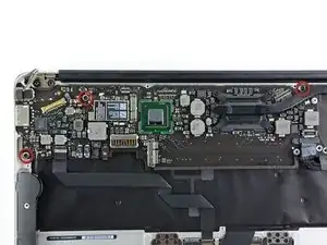
Entferne die drei 3,6 mm Torx T5 Schrauben, welche das Logic Board am oberen Gehäuse befestigen.
-
-
-
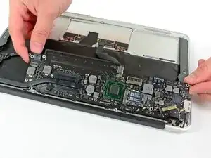
Hebe die Logic Board Einheit vorsichtig aus dem oberen Gehäuse, achte dabei auf den empfindlichen Kühlkörper und darauf,dass sich keine Kabel verfangen.
-
-
-
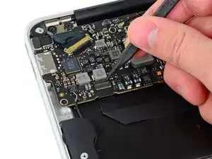
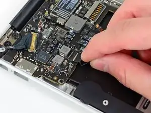
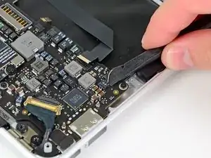
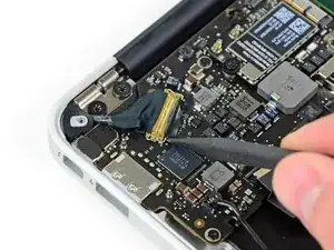
Klappe vorsichtig den Sicherungsbügel am ZIF-Anschluss des Mikrofonkabels mit der Spudgerspitze hoch.
-
Ziehe das Mikrofonkabel gerade aus seinem Anschluss heraus.
-
-
-
Hole das linke Lautsprecherkabel aus seinem Ausschnitt im I/O Board.
-
Hebele den Stecker des linken Lautsprecherkabels mit dem flachen Ende des Spudgers hoch und aus seinem Anschluss auf dem I/O Board heraus.
-
-
-
Ziehe das Kamerakabel parallel zur Oberfläche des I/O Boards in Richtung rückseitiger Kante des Air, um es aus dem Anschluss zu lösen.
-
-
-
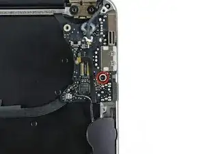
Entferne die einzelne 3,6 mm Torx T5 Schraube, welche das I/O Board am oberen Gehäuse befestigt.
-
-
-
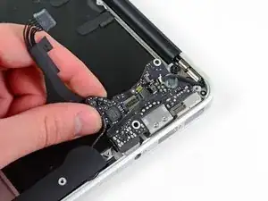
Hebe das I/O Board an der Kante nahe am Logic Board an und entferne es vom oberen Gehäuse.
-
-
-
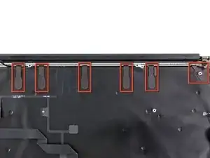
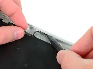
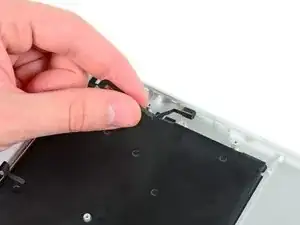
Löse die sechs Befestigungsschlaufen, die die Antennenkabel am oberen Gehäuse befestigen.
-
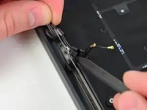
Ziehe die Befestigungsschlaufen nacheinander vorsichtig ein wenig aus den Einschnitten im oberen Gehäuse.
-
Öffne die Schlaufen mit einem Spudger, während du die Antennenkabel aus ihnen herausholst.
-
Wiederhole diesen Vorgang für alle restlichen Schlaufen.
-
-
-
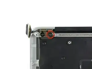
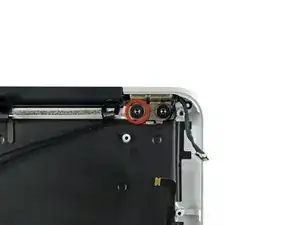
Entferne die innere 4,9 mm T8 Torx Schraube, welche jedes Displayscharnier am oberen Gehäuse befestigen (also insgesamt zwei).
-
-
-
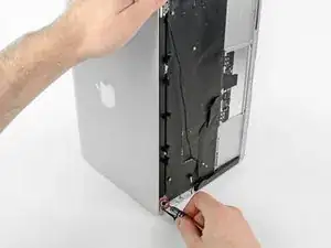
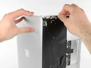
Öffne das Display, bis es senkrecht zum oberen Gehäuseteil steht und platziere es, wie auf dem Bild zu sehen ist, auf einen Tisch.
-
Während du das Air festhältst, entferne die übriggebliebene 4,9 mm T8 Torx Schraube von der unteren Displayklammer.
-
-
-
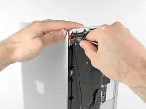
Entferne die letzte 4,9 mm T8 Torx Schraube, mit der das Display am oberen Gehäuseteil befestigt ist.
-
-
-
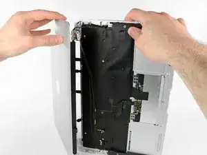
Schiebe das obere Gehäuse leicht in Richtung der Displayeinheit und drehe es dann weg von der Vorderseite der Displayeinheit.
-
Sobald die beiden Displayscharniere frei vom oberen Gehäuse sind, entferne das Display und lege es beiseite.
-
-
-
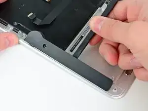
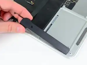
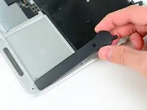
Hebele den rechten Lautsprecher mit dem flachen Ende des Spudgers aus der Klebeverbindung zum oberen Gehäuse.
-
Entferne den rechten Lautsprecher vom oberen Gehäuse.
-
-
-
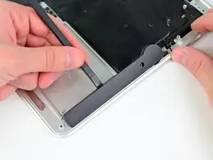
Hebele den linken Lautsprecher mit dem flachen Ende des Spudgers aus der Klebeverbindung zum oberen Gehäuse.
-
Entferne den linken Lautsprecher vom oberen Gehäuse.
-
-
-
Hebele das Mikrofon mit der Spudgerspitze weg von der Seite des oberen Gehäuses.
-
Entferne das Mikrofon vom oberen Gehäuse.
-
Das obere Gehäuse bleibt übrig.
-
Um dein Gerät wieder zusammenzusetzen, folge den Schritten in umgekehrter Reihenfolge.






When you say:
Remove the following ten screws:
Two 8 mm 5-point Pentalobe screws
Eight 2.5 mm 5-point Pentalobe screws
Do the 8mm & 2.5mm dimensions refer to the LENGTH of those screws, or the size of the pentalobe? That is, are there other sizes of pentalobe drivers like there are for hex, phillips and torx? When only one dimension is provided, it is usually the socket/driver size, not the screw length, maybe since the length cannot be seen when the screw is installed.
Can I suggest that you clarify your instructions so folks are confident they are only in need of _one_ pentalobe driver?
Nerdily yours,
Larry (whose iPhone 4S can now get through a day without 6 recharges thanks to ifixit.com ;-)
larryleveen -
The 8mm and 2.5mm are the length of the screws. One pentalobe P5 screwdriver suffices for all the screws (P5 is implicitly the size of the pentalobe screw heads).
Michael Welham -
I sourced all the parts from ifixit, plus a magnetic project mat which I found to be very useful for organising the teardown and reassembly.
Allen -
The magnetic mat is
GERARD SZAREK -
Keep the 2.5mm tiny screws away from the MagSafe connector as they will be attracted and sucked in to the magnet.
Frank O'Carroll -
A tip an old bench tech taught me that has saved me many times: I put clear “Scotch” tape over the case screws as they became “free”. The tape kept them in place while I lifted the lid off, cleaned it etc.
Michael Mee -
Thank you for a really smart tip! I will be using that countless more times!
Lilljedahl -
I’m confused about internet recovery and installing MacOS. Is all of this done before placing in the new ssd card or after. I don’t have any files that I would like to safe/transfer, is all of this necessary, if I don’t do it before placing new ssd, will I still be able to instal/upgrade macOS afterwards.
It’s an old Mac and now it won’t start or charge, I know I will have to replace battery and put new battery first and turn on Mac before doing the ssd stuff. Since it won’t effing start.
I’m really clueless about backing up old ssd, since I don’t need any files, besides MacOS(software) ,and is that related to the ssd?
AMG -
The answer to your question: You need to insert your SSD into the computer before internet recovery. If you start the recovery before inserting SSD, it won’t affect the setup, you won’t damage anything. But your SSD will not be detected (as there isn’t one inserted.)
Also, a little tip: If you bought a used SSD, go into Disk Utility and format the drive with the highest security level to permanently remove all of the previous files.
Also a FYI: Internet Recovery will load up Mac OS X 10.9.5 Mavericks, so I would recommend making a recovery drive from a Big Sur (or desired version) through another Mac, and a USB. You can visit this support doc: https://support.apple.com/en-us/HT201372
Hope this helps! -Dan
danielwen -
I got a macbook air with a damaged and swollen battery. I could remove all screws, except one 2,5 mm screw. I’m afraid it got damaged while attempting to remove it, I have no grip with the P5 pentalobe screwdriver. How can I proceed?
Robert Hermans -
Hi Robert!
Try some techniques found in this stripped screw removal guide. Good luck!
Arthur Shi -
Hello I have a macbook air they are say they do not have parts for my laptop macbook air 11 inches 2013 mid need to replace battery which one to buy
vensilver -
Hello! This is the part you want—maybe we’re not able to ship it to you if you’re out of the United States. The battery in your MacBook Air should be the same for all 11” between mid-2011 to early-2015.
Arthur Shi -
The smaller screws went in more easily when I put back all the screws along the hinge edge first.
Rachel Slatkin -