Einleitung

interne Voraussetzung

  1. RdamsPjnFjwQxD4g
    RdamsPjnFjwQxD4g
    NuZwJ1HKxf5JHlhq
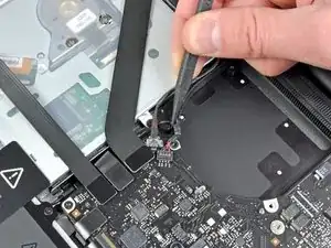
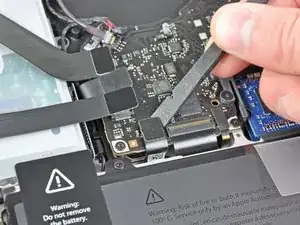
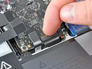
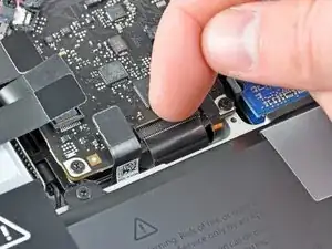
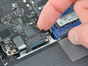
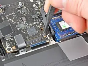
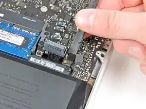
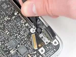
    • Ziehe das Kabel zum rechten Lautsprecher/Subwoofer mit der Spudgerspitze unter dem im oberen Gehäuse eingeformten Haltebügel heraus.

    • Ziehe das Kabel hoch, um den Verbinder aus seinem Sockel auf dem Logic Board zu heben.

    Reminder: When replacing the cable the connector should be placed in from above. This fooled me and I damaged the seat a bit, but not enough to prevent proper connection.

    Lee Hughart -

    Excellent guide, I feel this bit could be clearer tho. As it is a socket like a fan connector.

    Mine had a foam pad on the top like the other lift-up connections and I’ve accidentally taken the socket off.

    So just to be aware if your mac has the foam pad on top of this connection.

    acupton86 -

    I’ve broken the connector of the speaker (on the logic board) by installing it in the wrong way.

    Now, I ordered the connector from aliexpress, and have to do some micro soldering and hopefully it’ll work.

    Be careful guys

    iAziz -

    This one took me a moment to figure out. I also have the foam pad and couldn't see where the socket begins. Use the flat end of the spudger and go underneath the red/black cable part close to the socket, then slowly lift it up until it loosens a little, then do the same on the other side.

    Chris -

  2. siaE2U6svUdGP5v5
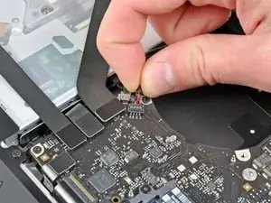
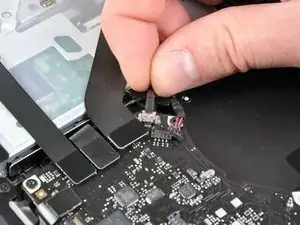
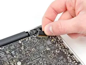
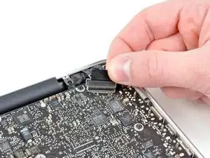
    • Löse das Kamerakabel vom Logic Board.

    • Ziehe das Kabel parallel zur Oberfläche der Platine. Wenn du das Kabel nach oben ziehst, kannst du das Kabel oder das Logic Board beschädigen.

    The camera cable head has bump at both sides. Just use two spudgers to pry it out.

    townbull -

    thank you great suggestion

    Soham Thacker -

    Here's where the mid-2009 13" MacBook Pro 5,5 makes its first major departure from this guide. No such connection exists. At least nowhere I could find on the motherboard.

    Larry Horton -

    IIRC the official service manual suggests putting the blunt or wide edge of a black-stick/spudger underneath the cable and then pressing down on said cable to provide better gripping force while pulling the cable out/away from the connector. It’s my tried-and-true method of choice.

    James -

    Anyone has a data of this cable becausei brkoe it and i have an other same connector ??

    Mail : mr.leminecrafteur@gmail.com

    VARE -

    Just broke this cable by pulling to hard. Definitely use a spudger to pry out the connector instead of pulling the cable.

    maxpoetter -

    Same, any suggestion about its replacement?

    giovanni.billet -

    Really grip those little bumps on the head with a pair of pliers and gently wiggle!

    moonsugar33 -

    In case you need replacement parts for the broken cable : http://www.powerbookmedic.com/MacBook-Pr...

    To find out how to replace the cable, you can have a look at this tutorial : https://fr.ifixit.com/Tutoriel/Remplacem...

    Guillaume Lamaison -

    Die Metallverbindung besteht aus zwei Teilen. Der kabelferne Teil drückt den Stecker nach unten. Der kabelferne Teil ist ein festgelöteter Schuh. Mit Hilfe einer dünnen Präpariernadel konnte ich den kabelzugewandten, beweglichen Metall-Teil der Verbindung zum einen horizontal herausschieben, zum anderen habe ich gleichzeitig gezogen. Nicht zu viel Kraft beim Ziehen aufwenden.

    Mir hat geholfen, ein Makrofoto vom Stecker zu machen, um ihn zu verstehen.

    hpw -

  3. HhyKlkRJwtMX2AmF
    HhyKlkRJwtMX2AmF
    RFP1wZ61QvypEeeF
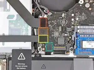
    • Löse folgende vier Kabel:

    • AirPort/Bluetoothkabel

    • Kabel zum optischen Laufwerk

    • Festplattenkabel

    • Kabel zum Trackpad

    • Um die Kabel zu lösen, musst du mit dem flachen Ende des Spudgers ihre Verbinder aus den Sockeln auf dem Logic Board heben.

    On the mid-2009 13" MacBook Pro 5,5 the Airport/Bluetooth cable is different from the other three cables in this step. It's fabric wrapped, and its connection works in a fashion more like the display data cable connection, although it does not have a lock that releases by pulling a tab back over the cable. So, to those of you who are repairing this model, be careful. Prying upward is not the way to remove this cable. I played with it until I could detect which parts were moving which way and why. Although I can't say with precision how the connection works, I removed it by gently coaxing slightly up at an angle and back along the plane of the optical drive. The idea is to pull the cable back out of its socket while lifting slightly.

    Too bad we can't post photos in the comments.

    Larry Horton -

    Same with the Mid 2010 model - moving the cable parallel to the board, towards the optical device works fine.

    Hans -

    It is advised to tape all those connectors out of the way of the mainboard. Use paper tape or paper labels as you want to avoid the electrical discharge associated with peeling off of plastic tape.

    dbovey -

  4. i3fce2IslTEKYL2m
    i3fce2IslTEKYL2m
    ServDjxJg2tMWKpK
    DknJ1eCCtm2yVViA
    • Klappe den Sicherungsbügel am Sockel des ZIF Verbinders des Tastaturflachbandkabels mit dem Fingernagel oder dem Spudger nach oben.

    • Passe auf, dass du wirklich nur den scharnierartigen Sicherungsbügel selbst bewegst, nicht den Sockel.

    • Ziehe das Flachbandkabel mit der Spudgerspitze aus dem Sockel.

    • Das Kabel lässt sich eventuell nicht wieder leicht einstecken. Wenn es schwer geht, kannst du zeitweise ein Stückchen Klebeband am Kabel anbringen, welches dir beim Einführen des Kabels hilft.

    Hello i've a late 2011 and have manged to break the keyboard ribbon cable ZIF socket. Is this a part that can be replaced? Ribbon is still good just the plastic has broken on the edge. Thanks

    Derek Cowan -

    No, You'll need to replace the logic board. I'd probably just use a wired or bluetooth keyboard and put the money towards a new machine.

    maccentric -

    I ran into trouble reattaching the keyboard ribbon cable into the ZIF socket. I couldn't grasp it in a way that let me push it all the all back. A local repair guy told me his trick: use a piece of tape. Attach a piece of tape to the ribbon cable and make a tab so you can pull the cable into the socket. Use of a piece of tape that you can easily remove. Works like a charm.

    David -

    Buy that man a pint! I've been working on computers professionally for a decade and I've never thought of that trick. Brilliant!

    Gryyphyn -

    Amazing this saved me!

    Felipe Cordero -

    You've saved me countless hours of crying trying to simply push it in

    Tunipguy -

    Thanks! This saved me hours!

    Marc Steffen -

    Thank you so much. Very clever idea that works like a charm!

    Todd Walls -

    Thank you so much! After 15 minutes of frustration, it inserted in less than 5 seconds.

    Todd Walls -

    I didin't read this before, but it was the idea i had in the moment... after 30 minutes of struggle. Thanks!

    Franco Iván Bello Rojas -

    After I put it all back together, the keyboard didn’t work; I traced it to this cable not being plugged in all the way. I used the tape trick to coax it all the way in to seat well and it works like a charm.

    Ruedi Schubarth -

    Thanks for the tip about keyboard ribbon, saved me a major headache

    domhnallk -

    It’s worth pointing out that the lever to lift this is at the back of the connector and that you’re pulling it towards yourself - this then releases the plastic on top of the cable that’s holding it in place.

    Nick Watts -

    The tape tirck saved my bacon!! Thank YOU!

    Jonathan Davis -

    Thanks so much. This trick saved the day!!!!

    Rafael Giuliano -

    It is advised to tape this connectors out of the way of the mainboard. Use paper tape or paper labels as you want to avoid the electrical discharge associated with peeling off of plastic tape.

    dbovey -

    Der Sicherungsbügel kann leicht mit dem Fingernagel vom Mainboard um 90 Grad zu mir her geklappt werden. ACHTUNG: Genau lesen, filigrane Teile gehen leicht kaputt.

    hpw -

    The tape trick worked for the smaller keyboard backlight ribbon but not this bigger ribbon…. I might take it to a repair shop because I’m out of ideas. Anyone know any other solution? I think someone mentioned using a pencil eraser as a grip on another site… might try that.

    hi there -

  5. klYcZJtNcLgkIDkA
    • Wenn vorhanden, musst du den kleinen schwarzen Klebestreifen über dem Anschluss der Tastaturbeleuchtung abziehen.

    The bottom of the small strip has excellent adhesive which will re-stick upon reassembly without any problems. I handled the sticky side and even stuck it to a plastic tray without any issues. Which is to say the sticky-ness does not seem to wear off.

    airshack -

    This is the most difficult ribbon cable to reinsert. As noted in the comments for the keyboard ribbon cable above I’d recommend also using a a small piece of tape to help reinsert.

    Bill Kirby -

    I used Blu-Tac on the end of my spudger to provide a gentle grip to get it to slide in.

    moonsugar33 -

    It is advised to tape this connectors out of the way of the mainboard. Use paper tape or paper labels as you want to avoid the electrical discharge associated with peeling off of plastic tape.

    dbovey -

  6. DZq4dAQdIjUoPMEo
    DZq4dAQdIjUoPMEo
    RWbvrmYhRtq2LiH2
    HdpyKBrTbxpMTvnW
    • Klappe die Halteklappe auf dem ZIF Verbinder der Tastaturbeleuchtung mit dem Spudger oder dem Fingernagel nach oben.

    • Passe auf, dass du wirklich nur die Halteklappe selbst bewegst, nicht den Sockel.

    • Ziehe das Flachbandkabel zur Tastaturbeleuchtung aus seinem Sockel.

    The first time I reassembled the system I left this tiny ribbon connector under the logic board by accident. If your keyboard backlight no longer works after reassembly it’s because you forgot to reattach this small connector. Fortunately, I caught my mistake before securing the logic board screws. It’s an easy to miss item.

    airshack -

    It is advised to tape this connectors out of the way of the mainboard. Use paper tape or paper labels as you want to avoid the electrical discharge associated with peeling off of plastic tape.

    dbovey -

    What the part name, i accidently broken this part

    Sandy Mustika Alam -

  7. RHUVwpPYaADSkhMd
    • Ziehe den Verbinder zum Ruhesensor/Akkuanzeige mit dem flachen Ende des Spudgers aus seinem Sockel auf dem Logic Board.

    the sleep sensor/battery indicator were not included with my new case, i had to transfer them over from my old case. once the battery is out (step 22), you can see the three screws you need to remove in order to take it out. it’s also secured by adhesive. the button for the battery indicator will likely fall out (at least it did on mine) when you remove the board, so be careful not to lose it…my new case did come with the button for the battery indicator (even though it didn’t come with the board or cable), but i just re-used the old one.

    Matt -

    I forgot to place this tiny flex cable on top of the mainboard, and tried to recover it from under (lazy!) so I broke it.

    In general I would tape all those connectors out of the way of the mainboard. Use paper tape or paper labels as you want to avoid the electrical discharge associated with peeling off of plastic tape.

    dbovey -

    Update: the computer works even without this feature. Of course the led battery indicator does not work, but it is not a big loss.

    dbovey -

    Does it still sleep properly?

    maccentric -

  8. t6Q2QIc1DBntqioK
    t6Q2QIc1DBntqioK
    JUJuWnPTcBUl6QvC
    siHWG6K1tMXeFQLL
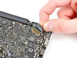
    • Fasse die Plastikzuglasche auf dem Sicherungsbügel des Displaydatenkabels an und drehe ihn in Richtung des DC-in Anschlusses des Computers.

    • Ziehe das Displaydatenkabel gerade aus seinem Sockel auf dem Logic Board.

    • Ziehe das Kabel nicht nach oben, denn sein Sockel ist sehr empfindlich. Ziehe das Kabel parallel zur Oberfläche der Platine.

    Its quite delicate, pull gently and it will pop out with a slight clicking sound

    Leo Jose -

    On my mid-2009 13" MacBook Pro 5,5 the display data cable was square with the motherboard, rather than at an angle. I'm not experienced with working on computer connections, but if I were going to describe this procedure, it would be more like:

    "Grasp the plastic tab on the end of the display data cable connection, and pull it gently back over the cable, toward the DC-in board. The tab is connected to a flat rectangular 'ring' that locks the cable to its connection, and when you pull the tab, the rectangular lock will flip back over the cable, allowing the cable to be removed by pulling the same direction, parallel to the surface of the motherboard."

    Larry Horton -

    Exactly the same as on the Mid2010 Model - never pull up, always parallel to the board, using the spudger to keep the cable down might helpfull while pulling with fingers the cable towards DC-In at the right side.

    Hans -

    My display is not working after reassemble the mac.

    Any reason?

    Nitin Sonwal -

    I had the same problem, and it was solved by slightly unscrewing the 14.4 mm screw that sits nearest the ESC button (upper left hand side, if the computer is open as if you’re using it). All the way screwed in, and the display conks out (something must be getting pinched). Slightly loosened, and the display immediately came back!

    Shannon Maguire -

    I choose not to remove this, just laid the board over. Worked just fine.

    Justin Patterson -

    I second this. It’s quite easy to leave this connection in place. The board flips over nicely, and everything is still accessible.

    Steven Weeks -

    I used my phone to photograph the entire underside of the Macbook Pro before I started removing things. This photo helped augment the excellent photos here. Take a few close-ups of each section/item before disassembly to reference upon assembly.

    airshack -

    when reattaching the display cable, i used the spudger to tuck the spongy top flap underneath the cable lock, so that i could then get the cable lock down the entire way. i couldn’t get it under there (and get the lock closed) without it, the top part of the display cable blocked it.

    Matt -

    When replaced the logic board when reassembled lap top screens not working. Saw others similar issues plugged in my monitor it’s working great must have messed up any ideas how to fix?

    Wayne McCarthy -

    Hi Wayne, and Michael! I had the same problem, and it was solved by slightly unscrewing the 14.4 mm screw that sits nearest the ESC button (upper left hand side, if the computer is open as if you’re using it). All the way screwed in, and the display conks out (something must be getting pinched). Slightly loosened, and the display immediately came back! —Shannon

    Shannon Maguire -

    My display is not working after I put everything back together, can hear the macbook chime. Tried shining light onto the display, see nothing. Tried loosening the screw slightly like someone suggested here, that does not help either. Tried cleaning the contacts of the LVDS cable, nothing. Any help appreciated.

    Don Seenu -

    This resolved it for me. My clasp wasn’t didn’t seem worn in any way but it seemed when it was clamped it caused the short circuit causing my screen to be black upon turning on. Lifting the clasp immediately resolved it. Odd issue! Thanks very much for the video. Incredibly helpful.

    Chris Gervais -

  9. qEvWyMNBEbJbG5BH
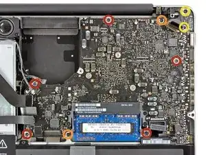
    • Entferne folgende neun Schrauben:

    • Fünf 3,6 mm T6 Torx Schrauben

    • Zwei 4,3 mm T6 Torx Schrauben

    • Zwei 7,2 mm T6 Torx Schrauben

    • Bei einigen Modellen sind die Schrauben, wie folgend beschrieben, unter Umständen etwas kürzer:

    • Fünf 3,0 mm Torx T6 Schrauben

    • Zwei 3,6 mm Torx T6 Schraube n

    • Zwei 6,7 mm Torx T6 Schrauben

    2 of the 7 listed 4mm screws attaching the logic board are actually 4.5 or 5 mm.... unfortunately. I didn't notice that until I was reassembling. so I don't know which positions they came from.

    starf1970 -

    I'm just noticing this too... I've put the longer screws as the two on the far left of the picture because they seemed to be the two holes I couldn't see the bottom to.

    ForumHermit -

    Just took one apart and paid attention this time. On this Mac, the screws colored orange should be red, and the 2 screws on the left side of the board should be orange (they’re a bit longer).

    maccentric -

    For keeping the screws straight I drew a simple diagram and placed them on it head down/threads up in their respective positions. Then all screws went back into their original positions without any guess work. Another suggestion I have during assembly is to start the screws without torquing them all the way down - leave them a little loose to allow some adjustment of the logic board for getting them all to line up with their holes, then torque them down. This technique also works for the screws on the bottom cover/lower case.

    Great guide! Saved me some dough, and now my MagSafe connector stays nice and cool.

    gregory mogle -

    for me the two on the farthest left were the 4.3mm screws. otherwise all went as described

    Levi Hoover -

    on something like this (like in iphones) i print the picture and place the screws on the picture. saves some problems and guessing.

    jeff chasalow -

    Well on my mid 2012 MacBook Pro the screw heads are definitely not T6 but rather J000. Will place the removed screws on a paper drawing of logic board. Good tip ….

    dontrep7a3 -

  10. EmuxSAVFeeWnUIpq
    EmuxSAVFeeWnUIpq
    uQijyfWaCtIrJUWs
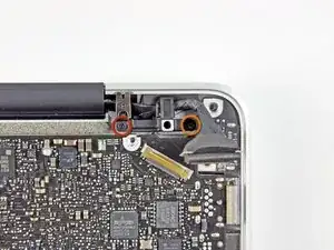
    • Entferne folgende zwei Schrauben:

    • Eine 8,6 mm Kreuzschlitzschraube

    • Eine 5,5 mm Kreuzschlitzschraube

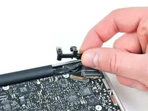
    • Entferne die Halterung des Displaydatenkabels vom oberen Gehäuse.

    Definitely not necessary to remove this bracket. You can disconnect the mic from the logic board and not have to deal with this bracket.

    kc7gnm77 -

  11. TSDkwsJJM3ZeunmW
    • Das Mikrofon ist am oberen Gehäuse festgeklebt. Löse es vorsichtig mit einer Spudgerspitze vom Kleber.

    Careful with this one. The wires are very thin fragile and it’s glued down very well making it extremely hard to remove. Just go slow and be patient otherwise you’ll damage the wires.

    Rob Kruit -

    I finally got that mic out by gripping it between two spudgers like a pair of chopsticks and gently pulling it out at an angle. The rubber shroud on it makes the thing hard to grip, and when I finally pulled it free, part of the adhesive ring tore off and stayed stuck to the chassis. When reassembling the machine, I had to kind of squish it back into place. It doesn’t hold quite as well as it did before, but it seems fine.

    Thomas -

    I managed to get the board out without prying the microphone off by twisting the board out while the microphone is still connected.

    You can then disconnect the microphone cable, which is a similar style connector to the fan cable and remove the board completely

    Alex -

    Vraiment pénible cette déconnection, allez y gentiment et la colle partira.

    raph raph -

    when reseating the logic board, first install the DC board in position and loosely seat the screws. then try to align the logic board to the 3.6mm screw housing closest to the firewire/ thunderbolt port and align the board to the ports and gently drop it into position. watch out for the cables that can get snagged under the board while seating it.

    Avocet Peregrine -

  12. IJie6MvkGZXLWiT1
    • Passe auf die vielen Anschlüsse am Rand auf und hebe das Logic Board am Ende beim optischen Laufwerk hoch.

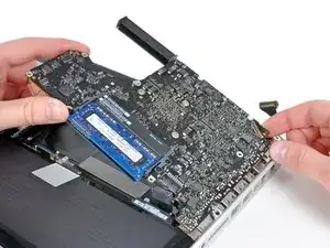
    • Biege die Platine nicht, wenn du sie aus dem Gehäuse heraushebst. Achte auf die flexible Verbindung zur DC-in Platine, die sich am Gehäuse verfangen könnte.

    • Entferne das Logic Board.

    I had the same issue. After wiggling the logic board back and forth and slowly applying more force, just up the threshold where I felt uncomfortable, it came out. The problem appeared to be caused by glue on the heatsink barcode sticking to the layer underneath.

    Shaun -

    I did all this, and worked! .but Im wondering, has anybody unscrewed what seems to be a mini heatsink (black 1 inch square housing) on the integrated GPU? Could I re apply paste on that?

    tony perry -

    I did make the change yesterday. inside it has a thermal pad, that appears to be 3mm or less. i try to clean on my best. I make a making a very tick pea size and added again. but i have no idea if it works or not. still having temps on 56c on idle. there is no much info on that. i use MX-4 from arctic. but i still, in my option, a little to for my use. if someone have more info on that part on the late 2011 i7 macbook pro 13inch please send the info.

    Carlos De Bernard -

    I did and applied Arctic Silver 5 underneath instead of the crap tape they put under there. This alone stopped the random freezing and rebooting problem I was having with this macbook pro. I recommend if you're already that deep into it, you might as well do it. I'm glad I did.

    ej257lgt -

    Need help. After I put everything back together, everything works fine but my macbook just wont charge. Any diagnosis on this? Anyone who can explain to me how the battery and the charging work in a Mac?

    justfinditjoshyip -

    If this happened to me, I would first suspect I hadn't completely connected the DC-in board cable. If I hadn't just replaced the battery, I would wonder if the battery was good. MagSafe power cable connect connections fail too, especially if they've been attached for a long time to a red hot DC-in board.

    If those failed, I'd head to the genius bar!

    Larry Horton -

    I had this problem. I accidentally cut the a cable from the DC-in board and I had to buy this component and replace it. You have to be very careful when mounting back the logic board in its position to not get a cable from the DC-in board cut by the screws.

    Enrique Cerrillo Cuenca -

    I broke the black backlight shield.... be careful when you feel the logic board and the film underneath it seem stickinig togethre.

    EUNAE JO -

    The fan exhaust grille was catching onto the speaker unit so I had to skip to step 28 to take it out. After taking out the airport card the speaker was able to move away from the fan grille and let me lift out the logic board.

    MrUnkownGuy -

    Also be sure to lift up the logic board to a slight angle so it clears the optical drive then pull it out gently at that angle. Do not pull it ulwards.

    MrUnkownGuy -

    The mainboard got stuck with the speaker and I can't lift it up. So I removed the first speaker screw (Wich is nearest to the mainboard) then I was able to remove the mainboard

    Mauricio Larrea -

    I removed the battery …. helps getting the logic board out.

    dontrep7a3 -

Abschluss

Um dein Gerät wieder zusammenzusetzen, folge den Schritten in umgekehrter Reihenfolge.

Andrew Bookholt

578335 Reputation

Ein Kommentar

If I have a MacBook Pro 13’’ A1278 Mid 2012 with i5 2.5GHz logic board, am I able to put a 2.3 GHz i5 A1278 early 2011 macbook pro logic board onto the Mid 2012 macbook pro?

Sara -