Einleitung

Wenn du Probleme beim Laden hast, hilft möglicherweise der Austausch der MagSafe Versorgungssplatine

  1. 2ycdtRrTgDZgPtCG
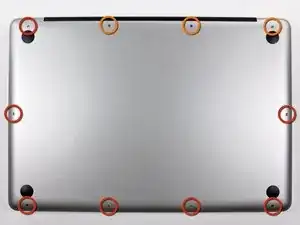
    • Entferne die folgenden zehn Schrauben, mit denen das untere Gehäuse am oberen Gehäuse befestigt ist:

    • Sieben 3 mm Kreuzschlitzschrauben

    • Drei 13,5 mm Kreuzschlitzschrauben

    May be helpful to have more distinct colors to identify the different screws.

    Victor Caamano -

  2. wyETETuUDDGNPgIh
    wyETETuUDDGNPgIh
    vLOGRGZI2eygR2sJ
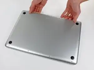
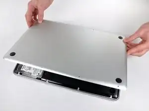
    • Hebe das untere Gehäuse mit beiden Händen in der Nähe der Lüftungsöffnung an, damit sich die beiden Clips lösen, mit denen die beiden Gehäuseteile verbunden sind.

    • Entferne das untere Gehäuse und lege es zur Seite.

  3. fBWga2JEZT2tmqRt
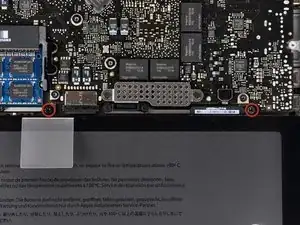
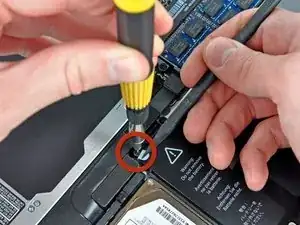
    • Entferne die beiden 5-Punkt Pentalobe Schrauben an der Oberkante des Akkus.

    • Wenn du die Festplatte austauschen willst, musst du nicht unbedingt den Schritten 3-7 folgen, um den Akku auszubauen. Allerdings ist es empfehlenswert, vor Reparaturen oder Wartungen immer alle Stromquellen von Elektrogeräten abzutrennen.

    Question: why do you remove the battery? According to Apple's official manual, this is not required (not for the mid-2009 and not for the mid-2010 15-inch MacBook Pro) - see pages 37 ff:

    http://manuals.info.apple.com/en_US/MacB...

    http://manuals.info.apple.com/en_US/MacB...

    alexkli -

    Zitat von alexkli:

    Question: why do you remove the battery? According to Apple's official manual, this is not required (not for the mid-2009 and not for the mid-2010 15-inch MacBook Pro) - see pages 37 ff:

    http://manuals.info.apple.com/en_US/MacB...

    http://manuals.info.apple.com/en_US/MacB...

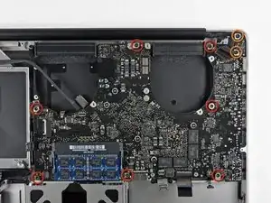
    I'm interested by your experience.

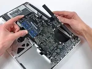
    Did you have removed the optical drive without removing the battery ?

    I'm just in this step now and if it is possible I would proceed like you because removing the battery void the warranty (and there is a sticker).

    Thanks in advance.

    youyou -

    Looks like my note to step 3 appears on all repair guides that have the same step. I meant that in the context of the hard drive replacement only.

    Did you have removed the optical drive without removing the battery ?

    I haven't yet done anything, waiting for my MacBook Pro 15 inch mid-2010 to arrive.

    alexkli -

    I missed the notes and went ahead and purchased the 5 point driver for the battery before I realized it was not necessary.

    I've edited the repair guide to remove the section on the battery, but I don't have the points to approve the changes.

    Chris Davis -

    Please note - the step about removing the battery is part of a pre-requisite guide, that is used for many of the guides, most that do require removal of the battery. Also, working inside a disassembled laptop with the battery still connected risks damaging/shorting out very expensive parts.

    Eric Essen -

    Absolutely. To be clear -- ALL of the above discussion is ONLY in reference to replacing the hard drive.

    Chris Davis -

    I replaced a hard drive in a MacBook Pro of an earlier model than this without removing the battery. The hard drive wasn't right. It only worked at about half speed, and I had to replace it once more. The second time I removed the battery and all went well. The recommendation by the iFixit staff to remove the battery before working on electronic equipment is a good one.

    doug -

    What is the size of those screws... I have rounded off the socket on mine and would like to replace them.

    Ghatothkach Yadav -

    I measured the screw size, using a micrometer, its about 1.523mm in diameter and 3.186mm in length. Not sure what screw size that is. They are not easily available I guess, unless someone is selling used ones on ebay

    Ghatothkach Yadav -

  4. 51GhiHAUMgp3IL1V
    • Biege die Ausbuchtung am Aufkleber "Warning: Do not remove the battery" mit der Spudgerspitze hoch, um die dritte Pentalobe Schraube darunter zu entfernen.

  5. DxGirDoRhQVXvY1S
    DxGirDoRhQVXvY1S
    iCPMLfZ6gsvCV1Gm
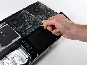
    • Hebe den Akku an seiner Plastiklasche hoch und schiebe ihn von der langen Kante des oberen Gehäuses weg.

    • Versuche noch nicht, den Akku ganz zu entfernen.

    Removing the battery is not necessary for the hard drive removal/replacement procedures.

    Erik -

    My T6 (appears to be same screw driver you have - $6 on amazon for 20piece set) did NOT fit int he battery screws...not sure if I had the wrong screws or what, but I went ahead w/o battery steps and it was pretty easy.

    Anthony Ettinger -

    I also noticed that the new SDD (from crucial) didn't have the 4 screws, so I had to move those off the old HD and onto the new one.

    Anthony Ettinger -

    Just had the same issue: T6 does not fit the battery screws ;-( ... but with a little bit more preassure it was possible to remove the screws.

    dirkvloenwagner -

  6. XfHIrygDNgEDWQtJ
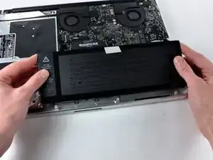
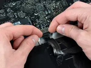
    • Kippe den Akku soweit nach hinten, dass du an den Akkukabelstecker herankommst.

    • Ziehe den Akkukabelstecker aus seinem Anschluss auf dem Logic Board und entferne den Akku aus dem oberen Gehäuse.

    • Wenn du einen neuen Akku einbaust, solltest du ihn nach dem Einbau kalibrieren.

    Excellent guide

    Kola Ajibade -

  7. wWoqXB3tSXcP13Fl
    wWoqXB3tSXcP13Fl
    rWHHku3mUNZMfGnT
    QfoCKkDHQ3GBEdJC
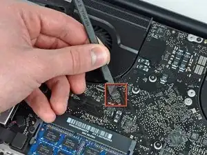
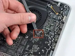
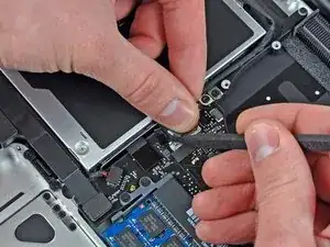
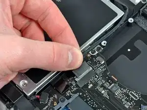
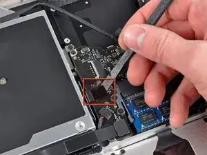
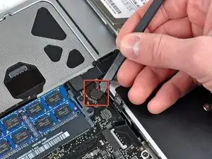
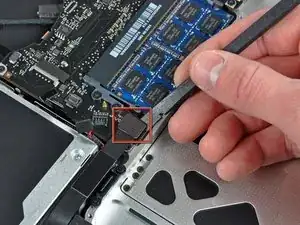
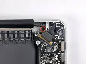
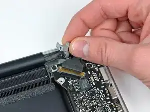
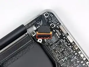
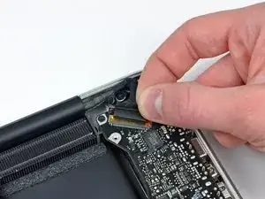
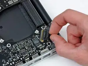
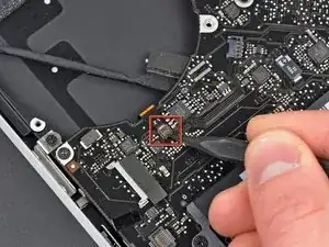
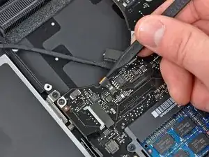
    • Löse den Stecker des Lüfters mit dem Spudger vom Anschluss auf dem Logic Board.

    • Es ist praktisch, den Spudger unter das Lüfterkabel zu setzen und dann der Länge nach zu verdrehen, damit sich der Stecker löst.

    • Der Anschluss und der Stecker des Lüfters sind im zweiten und dritten Bild zu sehen. Achte darauf, den Plastiksockel des Lüfters beim Abheben des Steckers mit dem Spudger nicht vom Logic Board zu brechen. Möglicherweise sieht das Logic Board im zweiten Bild etwas anders aus, wie bei dir, aber der Lüftersockel ist gleich.

  8. dQrcSKWAAd3ss3LU
    dQrcSKWAAd3ss3LU
    BkT4TeF2EkFaEm5g
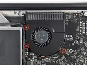
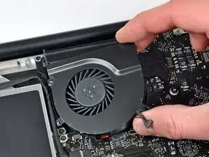
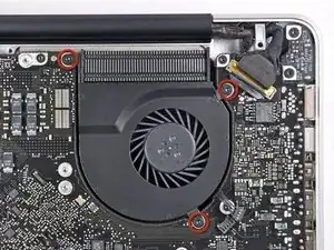
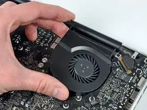
    • Entferne die drei Torx T6 Schrauben, mit denen der linke Lüfter am Logic Board befestigt ist.

    • Hebe den Lüfter aus dem oberen Gehäuse.

    Top left screw in this picture isn't a torx screw, and should be left in place. The screw you want is a bit further down than the one circled.

    digitalwraith -

    Good catch! It's fixed now.

    Andrew Bookholt -

  9. khFTbKCisX4wfS5Y
    • Trenne den Stecker des linken Lüfters mit dem flachen Ende des Spudgers vom Logic Board ab.

    • Heble von unter den Kabeln her.

    I didn't understand the description of the step to remove the fan connectors and I broke them both off. However! If anyone else does this, don't panic, the soldered connections are not electrical; they're just there to secure the fan connector. If you have the equipment you may be able to solder them back on, but I just put the whole thing back together - carefully sliding the jack back over the pins - and held it down with polyimide tape. I am using my Macbook Pro right now and the fans are definitely working.

    thesqueedler -

    For my Mid 2009 Macbook Pro, I only had one fan, so didn't have to do step 9 and 10.

    anonymous 7084 -

  10. aiOJoPQ6kNqUQWZV
    aiOJoPQ6kNqUQWZV
    RYvqFChLRKT1C6qy
    • Entferne die drei Torx T6 Schrauben, mit denen der linke Lüfter am Logic Board befestigt ist.

    • Hebe den linken Lüfter aus dem oberen Gehäuse heraus.

    For my Mid 2009 Macbook Pro, I only had one fan, so didn't have to do step 9 and 10.

    anonymous 7084 -

  11. dKVER2KyRU3mXHZU
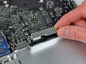
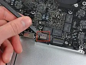
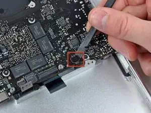
    • Apple hat ein kleines Stück durchsichtigen Kunstoffs auf einer Seite des Logic Boards hinter das Kamerakabel geklebt, damit der Stecker im Anschluss drin bleibt. Achte beim Entfernen darauf, dass du keine oberflächenmontierten Bauteile auf dem Logic Board beschädigst.

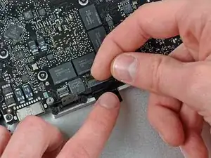
    • Halte den Halter des Kabels an einem Ende mit dem Finger nach unten, hebe das andere Ende ein wenig mit der Spudgerspitze hoch und drehe es vom Kamerakabelstecker weg.

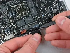
    • Ziehe das Kamerakabel gerade aus seinem Anschluss auf dem Logic Board heraus.

    • Ziehe den Stecker parallel zur Oberfläche des Logic Boards, nicht senkrecht zu ihr.

    Could not figure out what this step was telling me to do. The warning made me very cautious. Never got the board out because of this step. (Then I broke the subwoofer, but I can live with that.)

    boz -

    I’ve tried to clear things up in a pending modification, since I also had problems getting the point of this step. Hope it helps.

    Mihai Moldovan -

    The “strip” is the shiny black thing on the photo. The tip of the spudger is “pointing” at it on the photo. In fact it is already pushing the “strip” out of the way to be able to pull out the connector.

    glitter challenge -

    I finally got my system back together & running so much cooler after removing, cleaning the heat sink & repasting the CPU die & the two GPU dies. But working backward from this step to put it back together was most arduous: neither camera nor WiFi/Bluetooth worked when I first put the system back together. This is because it was hard to gauge that this connector was indeed back together and hold it so, based on 12 year-old fabric-padded adhesive alone. In the end, I checked that no pins in the connector were bent, guided them in as firmly as a flat spudger (not my hand, which twisted the cable at an angle) would allow, held it in the connector bay with electrical tape, put the fabric cushion back on top of that, and electrical taped across the cushion, between the connector bay and the cable. Phew! After tons of trial and error, put the system back together & both WiFi/Bluetooth and the camera work again!

    jonnywot -

  12. 1WKlqrLujRhFRZR2
    • Ziehe das Kamerakabel gerade aus seinem Anschluss auf dem Logic Board heraus.

    • Ziehe den Stecker parallel zur Oberfläche des Logic Boards, nicht senkrecht zu ihr.

  13. CkNL5haAxqRU2DUX
    • Heble den Stecker am Kabel zum optischen Laufwerk mit dem flachen Ende des Spudgers vom Logic Board weg.

  14. PmQIQ1UYDsUeQfHC
    • Heble den Stecker zum Tieftöner mit dem flachen Ende des Spudgers gerade aus seinem Anschluss heraus.

    • Sei sorgfältig und heble nur am Stecker, nicht am Anschluss. Wenn du unvorsichtig bist, kannst du versehentlich den Anschluss vom Logic Board abhebeln.

    • Wenn du den Schaumstoff entfernst, der oben am Stecker angebracht ist, dann siehst du besser und vermeidest ein Abhebeln des Anschlusses.

    Not sure what this is supposed to do. I tried to gently pry subwoofer off but it broke. :-(

    boz -

    guy's this is the same kind of connector as the fan is and it would better to use the axial twist technique then pulling up at the connector side like i did and damaged the subwoofer connector...

    repping -

  15. ErfksSKkQPl2Pdqe
    • Heble den Stecker am Kabel zur Festplatte/Infrarotsensor mit dem flachen Ende des Spudgers vom Logic Board weg.

  16. sEFBef2gMlPlRYGU
    sEFBef2gMlPlRYGU
    PZpuCVHRWX6nNRVl
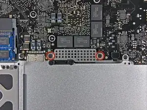
    • Entferne die beiden 1,5 mm Kreuzschlitzschrauben, mit denen die Kabelabdeckung am Logic Board befestigt ist.

    • Hebe die Kabelabdeckung aus dem oberen Gehäuse heraus.

  17. YyLCXNEyWvnym4iQ
    • Heble den Stecker am Flachbandkabel zum Trackpad mit dem Spudger vom Logic Board weg.

  18. PVRKBIQUrYdA2EAA
    PVRKBIQUrYdA2EAA
    42VMCgpoBIIdOyvM
    • Klappe den Sicherungsbügel am ZIF-Anschluss des Tastaturkabels mit dem Fingernagel hoch. Die Verriegelungsklappe befindet sich gegenüber vom Anschluss im Vergleich zum Tastaturkabel. Schiebe deinen Fingernagel darunter und hebe sie senkrecht hoch.

    • Versuche nicht, das Tastaturkabel aus seinem Anschluss zu schieben, bevor du den ZIF-Anschluss entriegelt hast. Flachbandkabel sind sehr empfindlich und können leicht kaputt gehen.

    • Schiebe das Tastaturkabel mit der Spudgerspitze aus seinem Anschluss heraus.

  19. sGMQfURkCEOJKE1L
    • Heble den Stecker am Flachbandkabel zur Akkuanzeige mit dem Spudger vom Logic Board hoch.

  20. I42mIDNRgdqsv235
    I42mIDNRgdqsv235
    sk3BGmPSD5KAjP5O
    • Entferne die einzelne 7 mm Kreuzschlitzschraube, welche den Halter des Displaydatenkabels am oberen Gehäuse befestigt.

    • Diese Schraube bleibt möglicherweise in der Erdungsöse des Displaydatenkabels hängen. Wenn du das Display austauschst, musst du diese Schraube auf dein Ersatzteil übertragen.

    • Entferne den Halter des Displaydatenkabels vom oberen Gehäuse.

  21. uvLKddVxsMIGoITH
    uvLKddVxsMIGoITH
    fVnTkMh6JXBvSWnh
    • Fasse die Plastikzuglasche an der Verriegelung des Displaydatenkabels und drehe sie zur Seite mit der Gleichspannungsversorgung am Computer.

  22. P6WruYylJOChFT6R
    • Ziehe den Stecker am Displaydatenkabel gerade aus seinem Anschluss heraus.

    • Achte darauf, dass du den Stecker parallel zur Oberfläche des Logic Boards ziehst und nicht senkrecht zu ihr.

  23. 6QSFognjTrFldZuI
    6QSFognjTrFldZuI
    4f1bvb4uespafgcE
    • Klappe den Sicherungsbügel am Flachbandkabel der Tastaturbeleuchtung mit der Spudgerspitze hoch.

    • Ziehe das Flachbandkabel der Tastaturbeleuchtung gerade aus seinem Anschluss heraus.

  24. KSaXwLPPuExt5TvZ
    • Entferne folgende Schrauben:

    • Sieben 3,3 mm Torx T6 Schrauben, mit denen das Logic Board am oberen Gehäuse befestigt ist.

    • Zwei 8 mm Torx T6 Schrauben, mit denen die Platine der Gleichspannungsversorgung am oberen Gehäuse befestigt ist.

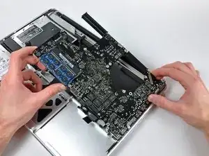
    • Entferne das Logic Board noch nicht! An der Unterseite des Logic Boards befinden sich noch Komponenten, die mit dem oberen Gehäuse verbunden sind, und zuerst noch abgetrennt werden müssen.

    For my Mid 2009 Macbook Pro, in Step 24 I had 8 3.3mm T6 Torx, not 7.

    anonymous 7084 -

  25. WrpJNDAK1fT6c4pV
    • Hebe das Logic Board sorgfältig an der linken Seite an und hole es aus dem oberen Gehäuse heraus. Achte dabei auf die Seite mit den Anschlüssen, die sich möglicherweise verfangen können.

    • Entferne das Logic Board noch nicht!

  26. YMlB3OgKBlI6LjLU
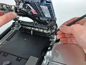
    • Hebe das Board soweit an, dass du mit einem Spudger das Mikrofon vom oberen Gehäuse hebeln kannst.

    • Schiebe das Logic Board von den Anschlussöffnungen weg und hebe die Einheit aus dem oberen Gehäuse heraus.

    • Bevor du das Logic Board wieder einbaust, ist es am einfachsten, wenn du das Mikrofon in seine Öffnung im linken Lautsprecher wieder eindrückst, damit es an seinen Platz bleibt.

  27. O5jhuMDXoC5XF5Ow
    • Schiebe das Logic Board von den Anschlussöffnungen weg und hebe die Einheit aus dem oberen Gehäuse heraus.

    • Bevor du das Logic Board wieder einbaust, ist es am einfachsten, wenn du das Mikrofon in seine Öffnung im linken Lautsprecher wieder eindrückst, damit es an seinen Platz bleibt.

  28. pM53lYZj1c1jDBJU
    • Lege das Logic Board auf eine flache weiche Oberfläche, so dass der Kühlkörper nach oben zeigt.

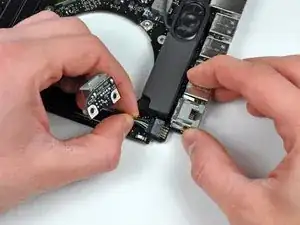
    • Ziehe den Stecker der Gleichspannungsversorgung gerade aus seinem Anschluss heraus und trenne ihn ab.

Abschluss

Um dein Gerät wieder zusammenzusetzen, folge den Schritten in umgekehrter Reihenfolge.

Andrew Bookholt

578335 Reputation

10 Kommentare

Great guide. The locking flaps in Steps 18, 21 and 23 are a little hard to decipher in the pictures. I accidentally pulled out the keyboard ribbon cable without unlocking its retaining flap, but I apparently got it in back correctly (after lifting the flap) and didn't break anything because everything works now. This has solved the charging problems I've had for years. I should be able to get a couple more useful years out of this machine now.

lurbano -

Great guide. For my Mid 2009 Macbook Pro, I only had one fan, so didn't have to do step 9 and 10. Also in Step 24 I had 8 3.3mm T6 Torx, not 7. Other than that was perfect!

anonymous 7084 -

How long did it take you Anonymous 7084?
Mauricio Toscano -

Very good guide. It worked out perfectly for me. It takes around 45 minutes to complete.

Terry Dillon -

Question: In My late model 2011 MacBook Pro is the pin port replaceable? The actual pins? It looks from the photo (step 28) as though it is adhered to the board. The receiving pins in the port in my Notebook are burning away and charging plug contact is greatly affected.
Amster Dam -

I replaced the MagSafe board following this guide, as the pins in the old one were bent and crufty.

I now see a dim green light when connected to the new MagSafe port. However, I press the power button, and nothing happens. I disconnected the power source and took off the cover to maker sure all of the connections were re-connected. Everything, at least that’s visible without removing the logic board again.

Any suggestions on how to troubleshoot this?

Mr Brico -

Excellent guide. Easy to follow and now my MacBook works again. Thanks!

Simon -

Thanks for these detailed instructions! Can I use this guide and the tools for a 13 Inch Mac Book Pro as well? Cheers, Antje

Antje van Oosten -

I meant this one: MacBook Pro (13-inch, medio 2012)

Antje van Oosten -

Oh I’m sorry, I found the right guide!

Antje van Oosten -