Einleitung
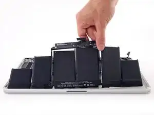
Anhand dieser Anleitung kannst du den eingeklebten Akku mithilfe eines iFixit Akku Kits sicher aus deinem MacBook Pro entfernen. Der Klebstoff-Entferner in deinem Kit löst den Kleber, der den Akku fixiert, und ermöglicht es dir so, ihn mühelos zu entfernen.
Der iFixit Klebstoffentferner ist leicht entzündlich. Führe diesen Austausch in einem gut belüfteten Bereich durch. Du solltest währenddessen nicht rauchen oder in der Nähe einer offenen Flamme arbeiten.
Um das Sicherheitsrisiko zu verkleinern, solltest du den Akku deines MacBook Pro vollständig entladen, bevor du mit der Reparatur beginnst. Ein geladener Lithium-Ionen-Akku kann ein gefährliches und unkontrollierbares Feuer verursachen, wenn er versehentlich beschädigt wird. Wenn dein Akku aufgebläht ist, dann musst du geeignete Vorsichtsmaßnahmen treffen.
Hinweis: Das Lösungsmittel, das zum Lösen des Akkuklebers verwendet wird, wird deine Lautsprecher beschädigen, wenn es mit deren Kunststoffgehäusen in Berührung kommt. In dieser Anleitung wird der Lautsprecher entfernt, bevor mit dem Akku weitergemacht wird.
Wenn du noch den veralteten iFixit Klebstoffentferner verwendet, bei dem die Flasche und die Spritze getrennt sind (wird nicht mehr verkauft), dann
klicke hier für eine leicht geänderte Version dieser Anleitung.
Werkzeuge
Ersatzteile
-
-
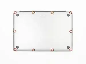
Entferne die folgenden P5-Pentalobe-Schrauben, mit denen das Gehäuseunterteil am MacBook Pro befestigt ist:
-
Acht 3,0 mm Schrauben
-
Zwei 2,3 mm Schrauben
-
-
-
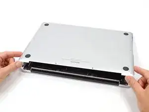
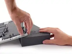
Hebe das Gehäuseunterteil von der Kante aus, die der Kupplungsabdeckung am nächsten liegt, vom MacBook Pro ab.
-
Lege das Gehäuseunterteil beiseite.
-
-
-
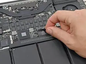
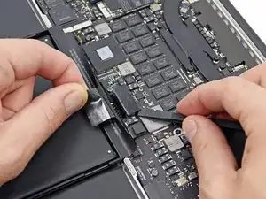
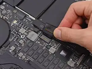
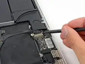
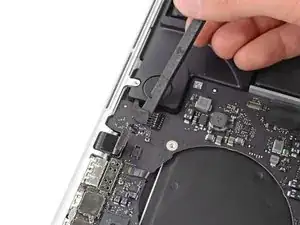
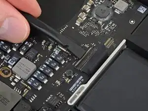
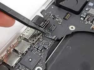
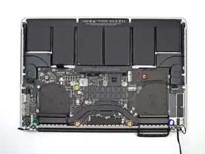
Heble den Akkuanschluss mit dem flachen Ende eines Spudgers vorsichtig aus seiner Buchse auf dem Logic Board heraus.
-
Biege die Akkukabel nach hinten und aus dem Weg, so dass der Akkuanschluss nicht versehentlich mit dem Logic Board in Kontakt kommt.
-
-
-
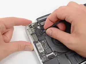
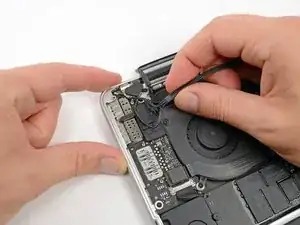
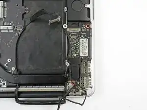
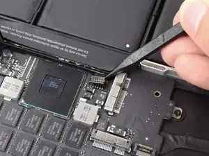
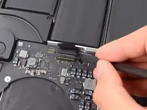
Mit einem Spudger oder einer Pinzette kannst du die drei AirPort-Antennenkabel senkrecht aus ihren Buchsen auf dem AirPort-Board herausziehen.
-
-
-
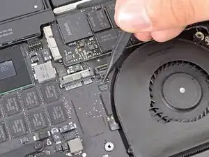
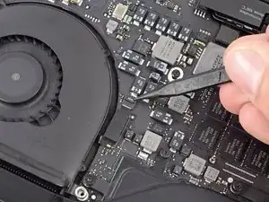
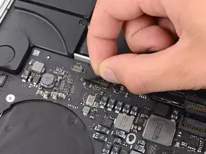
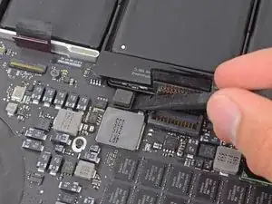
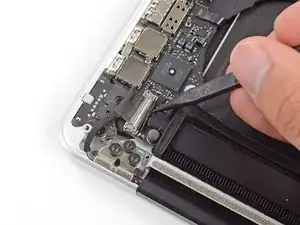
Schiebe den Stecker des Kamerakabels mit der Spudgerspitze aus seinem Anschluss auf dem Logic Board in Richtung des Lüfters.
-
-
-
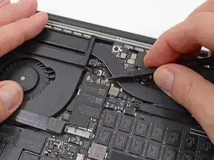
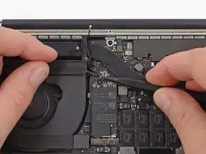
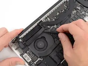
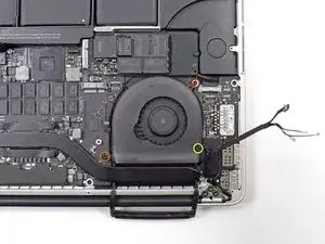
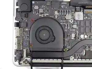
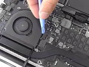
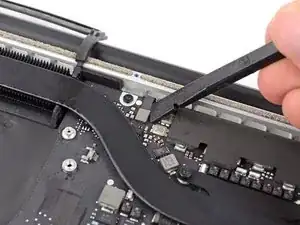
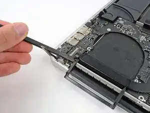
Stecke das flache Ende eines Spudgers unter die Gummiummantelung des Kühlkörpers des rechten Lüfters.
-
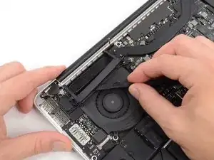
Fahre mit dem Spudger unter der gesamten Länge der Ummantelung entlang, um den Kleber zu lösen.
-
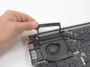
Hebe die Ummantelung an und klappe sie zurück, so dass du an die Kabel darunter herankommst.
-
-
-
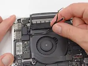
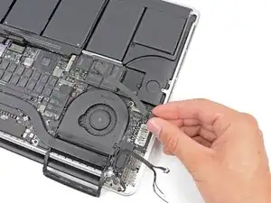
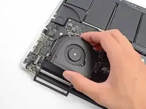
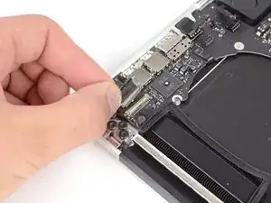
Ziehe die AirPort / Kamera Kabel mit den Fingern nach oben vom Lüfter ab.
-
Fädle die Kabel vorsichtig aus ihrer Kunststoffführung.
-
-
-
Wenn die Stecker am Kabel zum I/O-Board auf der Oberseite Einbuchtungen haben, dann müssen zuerst Verriegelungen unter der Einbuchtung gelöst werden, bevor das Kabel abgetrennt werden kann. In diesem Fall darfst du den Stecker erst dann hochhebeln, wenn der Verriegelungshebel offen ist.
-
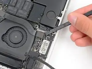
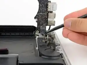
Heble den Stecker des I/O-Boards mit dem flachen Ende eines Spudgers aus seiner Buchse auf dem Logic Board heraus.
-
Entferne auf die gleiche Weise den I/O-Board-Kabelstecker aus seinem Anschluss auf dem I/O-Board.
-
Entferne das I/O-Board Kabel vom MacBook Pro.
-
-
-
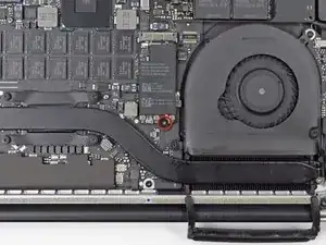
Entferne die einzelne 2,9 mm T5 Torx (manchmal auch T6) Schraube, mit der die AirPort Karte am Logic Board befestigt ist.
-
-
-
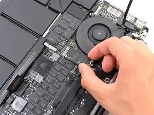
Fasse die Airport-Karte an den Seiten an und hebe sie leicht schräg (in einem Winkel von etwa 5 - 10°) hoch. Sie löst sich so aus der schwachen Klebeverbindung zum Logic Board.
-
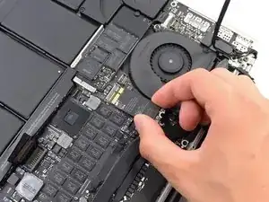
Ziehe die Airport-Karte parallel aus ihrem Anschluss auf dem Logic Board heraus und entferne sie.
-
-
-
Klappe den Sicherungsbügel am rechten ZIF-Anschluss des Ventilator-Flachbandkabels mit der Spitze eines Spudgers nach oben.
-
Platziere ein Plastiköffnungswerkzeug ganz oben unter das rechte Lüfterkabel und schiebe es dann nach unten, um das Kabel vom Logic Board zu lösen.
-
-
-
Entferne die folgenden drei Schrauben, mit denen der rechte Lüfter am Logic Board befestigt ist:
-
Eine 4,4 mm T5 Torx Schraube
-
Eine 3,9 mm T5 Torx Breitkopfschraube
-
Eine 5,0 mm T5 Torx Schraube mit 2 mm Zapfen
-
-
-
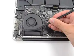
Stecke das flache Ende eines Spudgers unter die Gummiummantelung des Kühlkörpers des linken Lüfters, damit du sie herunternehmen kannst.
-
-
-
Entferne die folgenden drei Schrauben, mit denen der linke Lüfter am Logic Board befestigt ist:
-
Eine 4,4 mm T5 Torx-Schraube mit 2 mm Bund
-
Eine 5 mm T5 Torx Schraube mit 2 mm Bund
-
Eine 3,9 mm T5 Torx Breitkopfschraube
-
-
-
Klappe den Sicherungsbügel am ZIF-Anschluss des linken Ventilator-Flachbandkabels mit der Spitze eines Spudgers nach oben.
-
Schiebe ein Plastiköffnungswerkzeug von oben unter das linke Lüfterkabel, um das Kabel vom Logic Board zu lösen.
-
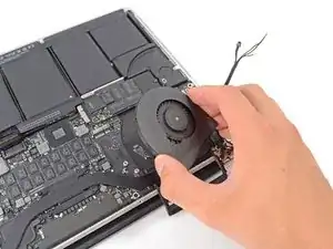
Hebe den linken Lüfter aus dem Gerät.
-
-
-
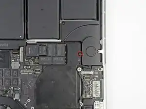
Entferne die einzelne 3,1 mm T5 Torx-Schraube, mit der die SSD am Logic Board befestigt ist.
-
-
-
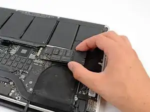
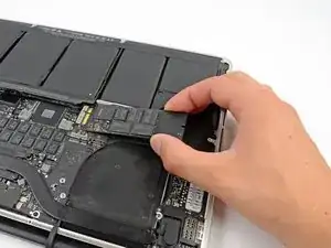
Hebe die rechte Seite der SSD leicht an und schiebe sie aus ihrer Buchse auf dem Logic Board heraus.
-
-
-
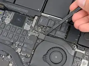
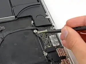
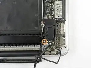
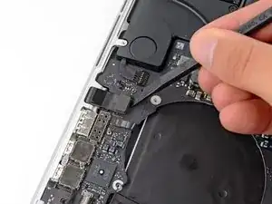
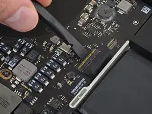
Verwende die Spitze eines Spudgers, um den Verschluss des I/O-Board Datenkabels nach oben zu klappen und es Richtung Akku zu drehen.
-
Verwende das flache Ende eines Spudgers, um das Datenkabel des I/O-Boards aus seiner Buchse auf dem Logic Board herauszuziehen.
-
-
-
Entferne die beiden 3,1 mm T5 Torx-Schrauben, mit denen das I/O Board am Logic Board befestigt ist.
-
Bei manchen Modellen hilft es beim Ausbau des I/O Boards zusätzlich, wenn du auch die silberne 3,5 mm Torx T5 Schraube vom Kühlkörper entfernst.
-
Hebe das I/O Board vorsichtig an und entferne es aus dem unteren Gehäuse.
-
-
-
Verwende das flache Ende eines Spudgers, um die Kopfhörerbuchse von ihrem Anschluss auf dem Logic Board nach oben abzuziehen.
-
-
-
Verwende das flache Ende eines Spudgers, um den linken Lautsprecheranschluss aus seiner Buchse auf dem Logic Board herauszuziehen.
-
Benutze die Spitze eines Spudgers, um den rechten Lautsprecheranschluss aus seiner Buchse auf dem Logic Board herauszuziehen.
-
-
-
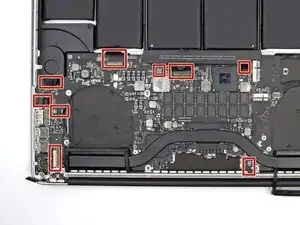
Wenn sich Klebeband auf dem Stecker des Tastatur-Flachbandkabels befindet, dann ziehe es davon ab.
-
-
-
Klappe den Sicherungsbügel am ZIF-Anschluss des Flachbandkabels der Tastatur mit dem flachen Ende des Spudgers hoch.
-
Ziehe das Tastatur-Flachbandkabel mit dem flachen Ende des Spudgers aus dem Anschluss heraus. Drücke erst auf einer, dann auf der anderen Seite.
-
-
-
Verwende das flache Ende eines Spudgers, um den Anschluss des Trackpad-Flachbandkabels von seiner Buchse auf dem Logic Board zu hebeln.
-
-
-
Verwende das flache Ende eines Spudgers, um den Anschluss für die Hintergrundbeleuchtung der Tastatur von seiner Buchse auf dem Logic Board nach oben abzuziehen.
-
-
-
Klappe mit der Spitze eines Spudgers oder mit deinem Fingernagel die Halteklappe an der ZIF-Buchse des Mikrofon-Flachbandkabels nach oben.
-
Ziehe das Mikrofon-Flachbandkabel aus seiner Buchse.
-
-
-
Benutze die Spitze eines Spudgers, um den Verschluss des Display Datenkabels zu lösen und drehe es in Richtung des DC-In.
-
Ziehe das Display Datenkabel aus seiner Buchse auf dem Logic Board heraus.
-
-
-
Verwende das flache Ende eines Spudgers, um vorsichtig die Gummikappe der Linsenschraube in der Nähe des MagSafe 2-Steckers abzuhebeln.
-
-
-
Entferne die folgenden sechs Schrauben, mit denen das Logic Board am oberen Gehäuse befestigt ist:
-
Eine 2,6 mm T5 Torx Schraube
-
Zwei 5,8 mm T5 Torx Schrauben
-
Eine 3,8 mm T5 Torx Schraube
-
Eine 5,2 mm T5 Torx Linsenschraube
-
Eine silberne 3,5 mm T5 Torx Schraube
-
-
-
Hebe das Logic Board an der Seite an, die dem Akku am nächsten liegt und drehe es nach oben.
-
Drücke den MagSafe 2-Stecker vorsichtig mit dem flachen Ende eines Spudgers aus seiner Buchse auf der Unterseite des Logic Boards.
-
Im Uhrzeigersinn von oben: Tastatur, Trackpad, Akku, rechter Lautsprecher, Hintergrundbeleuchtung der Tastatur, Display, Mikrofon, Kopfhörerbuchse, linker Lautsprecher.
-
-
-
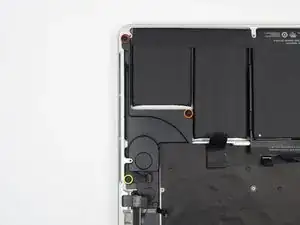
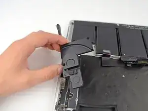
Entferne die folgenden drei Schrauben, mit denen der linke Lautsprecher am oberen Gehäuse befestigt ist:
-
Eine 5,6 mm T5 Torx Schraube
-
Eine 6,9 mm T5 Torx Schraube
-
Eine 2,6 mm T5 Torx Schraube
-
Hebe den linken Lautsprecher aus dem oberen Gehäuse heraus und lege ihn beiseite.
-
-
-
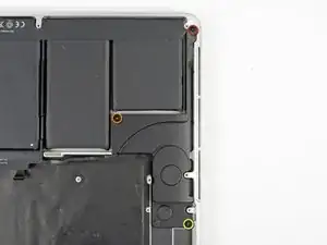
Entferne die folgenden drei Schrauben mit denen der rechte Lautsprecher am oberen Gehäuse befestigt ist:
-
Eine 5,6 mm T5 Torx Schraube
-
Eine 6,9 mm T5 Torx Schraube
-
Eine 2,6 mm T5 Torx Schraube
-
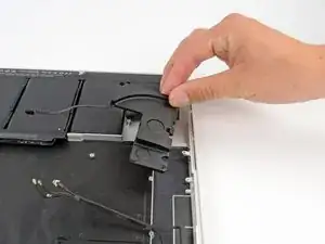
Entferne den rechten Lautsprecher aus dem MacBook Pro.
-
-
-
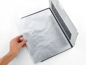
Lege eine Aluminiumfolie zwischen Display und Tastatur, um dein Display zu schützen. Die Folie sollte während des gesamten Arbeitsprozesses dort bleiben.
-
-
-
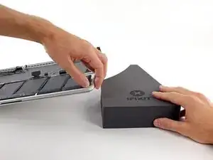
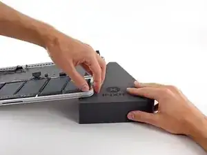
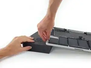
Die Vorderkante des MacBook Pro sollte zu dir zeigen. Hebe die rechte Seite an und schiebe einen stabilen Schaumstoffblock oder ein Buch unter, so dass das MacBook Pro leicht schräg steht.
-
-
-
Dein MacBook Pro ist jetzt gut vorbereitet, nun wird es Zeit, auch dich selbst vorzubereiten.
-
Wenn du mit dem Klebstoffentferner arbeitest und ihn aufbringst, solltest du immer deine Augen schützen. (Eine Schutzbrille ist in deinem Kit enthalten).
-
Insbesondere auch wenn du Kontaktlinsen trägst, musst du zusätzlich die Schutzbrille aufsetzen.
-
In deinem Kit sind auch Schutzhandschuhe enthalten. Wenn deine Haut empfindlich ist, solltest du die Handschuhe jetzt anziehen.
-
-
-
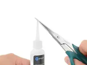
Ziehe den schwarzen Gummistopfen von dem Fläschchen mit Klebstoffentferner ab.
-
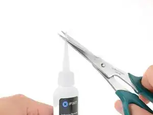
Schneide die verschlossene Applikatorspitze mit einer Schere ab.
-
-
-
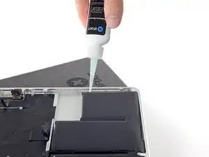
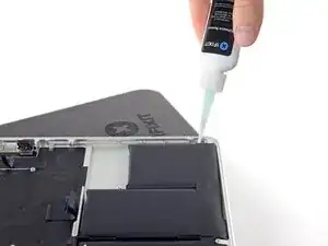
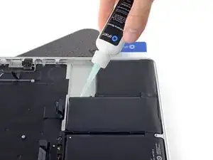
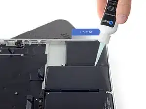
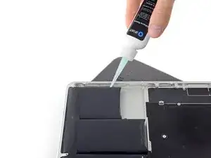
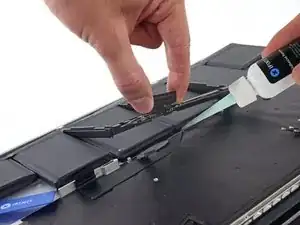
Gib einige Tropfen des Klebstoffentferners gleichmäßig am erhöhten Rand entlang auf die am weitesten rechts liegenden Akkuzelle.
-
Warte 2-3 Minuten, bis der flüssige Klebstoffentferner unter die Aktuelle eingedrungen ist, bevor du mit dem nächsten Schritt fortfährst.
-
-
-
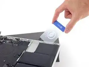
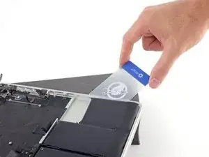
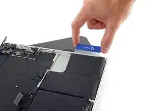
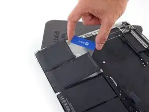
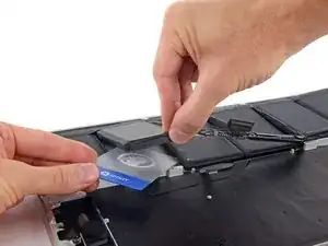
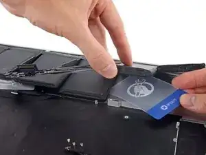
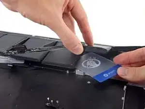
Setze die Ecke einer Plastikkarte unter dem äußeren Rand der Akkuzelle an.
-
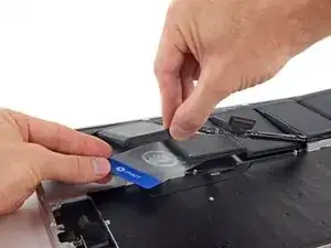
Führe die Karte weiter unter die Akkuzelle, um sie von dem Kleber zu lösen, mit dem sie in das obere Gehäuse des MacBook Pro eingeklebt ist.
-
-
-
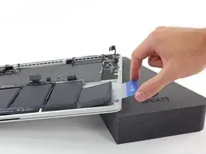
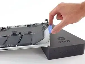
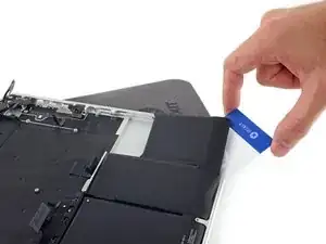
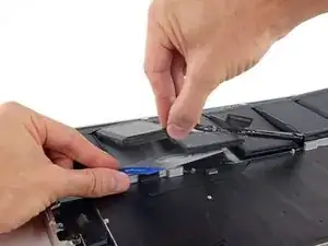
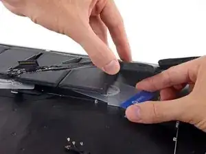
Hebe die Akkuzelle an, um sie vom oberen Gehäuse des MacBook Pro zu lösen, aber versuche noch nicht, sie ganz zu entfernen.
-
Lasse die Plastikkarte unter der Akkuzelle, damit sie nicht wieder festklebt, während du weitermachst.
-
-
-
Gib einige Tropfen des Klebstoffentferners gleichmäßig am erhöhten Rand entlang auf die nächste Akkuzelle.
-
Warte 2-3 Minuten, bis der flüssige Klebstoffentferner unter die Aktuelle eingedrungen ist, bevor du mit dem nächsten Schritt fortfährst.
-
-
-
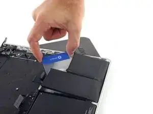
Schiebe eine Ecke deiner Plastikkarte unter die zweite Akkuzelle.
-
Drücke die Karte weiter unter die zweite Akkuzelle und schiebe sie hin und her, damit sich der darunterliegende Kleber löst.
-
Lasse die Plastikkarte unter beiden Akkuzellen (oder klappe sie um), damit sie nicht wieder ankleben, wenn du weitermachst.
-
-
-
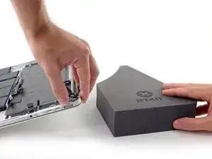
Es ist Zeit, die Seiten zu wechseln. Entferne dein Buch oder deinen Schaumstoffblock und lege ihn unter die gegenüberliegende Seite deines MacBook Pro.
-
Wiederhole den Vorgang aus den vorherigen Schritten, um die beiden Akkuzellen auf dieser Seite abzulösen:
-
Trage den Klebstoff-Entferner auf die erhöhte Kante der äußeren Akkuzelle auf und warte 2-3 Minuten, bis er einwirkt.
-
Drücke eine Ecke einer Plastikkarte unter die Akkuzelle und schiebe die Karte vollständig unter die Akkuzelle, um diese vom Kleber zu lösen.
-
Mache dasselbe bei der benachbarten Zelle.
-
Lasse deine Plastikkarte an Ort und Stelle oder klappe die Akkuzellen um, damit sie bei den folgenden Schritten nicht wieder anhaften.
-
-
-
Entferne dein Buch oder deinen Schaumstoffblock und lege ihn unter die hintere Kante deines MacBook Pro in der Nähe der Displayscharniere.
-
-
-
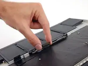
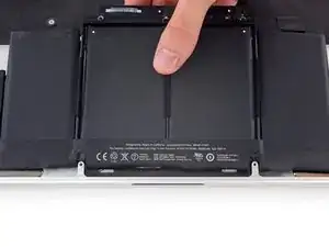
Nimm den Akkustecker oder die obere Kante des Kunststoffrahmens des Akkus und hebe ihn leicht an, so dass die obere Kante der beiden mittleren Akkuzellen freigelegt wird.
-
-
-
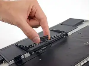
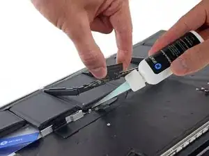
Hebe den Kunststoffrahmen des Akkus aus dem Weg und lasse ein paar Tropfen des Klebstoffentferners unter die Oberkante von jeder der beiden verbleibenden Akkuzellen laufen.
-
Warte 2-3 Minuten, damit der flüssige Klebstoffentferner einwirken kann, bevor du mit dem nächsten Schritt fortfährst.
-
-
-
Hebe den Kunststoffrahmen wieder aus dem Weg und drücke eine Ecke deiner Plastikkarte unter den äußeren Rand der ersten mittleren Akkuzelle.
-
Schiebe die Karte ganz unter der Akkuzelle und lasse sie dort, damit die Akkuzelle nicht wieder anhaftet.
-
-
-
Wiederhole den oben beschriebenen Vorgang, um die letzte verbleibende Akkuzelle vom oberen Gehäuse des MacBook Pro zu trennen.
-
-
-
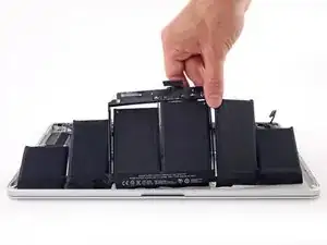
Hebe den Akku mit dem Kunststoffrahmen an und ziehe ihn nach hinten in Richtung Scharnier aus den Schraubstiften heraus, mit denen er am oberen Gehäuse befestigt ist.
-
-
-
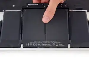
Hebe den Akku nun als Ganzes aus dem oberen Gehäuse heraus und entferne ihn.
-
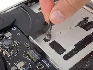
Mit etwas Glück kannst du jeden einzelnen Klebestreifen langsam mit den Fingern abziehen.
-
Falls das nicht klappt, träufle etwas Klebstoffentferner auf jeden Klebestreifen und lasse ihn 2-3 Minuten einwirken. Dann kannst du die Klebestreifen mit einem Plektron oder einem anderen geeigneten Werkzeug aus deinem Kit abkratzen. Das ist etwas langwierig, hier hilft dir nur Geduld!
-
Wische den restlichen Klebstoffentferner ab und lass dein MacBook Pro ein paar Minuten an der Luft trocknen.
-
Kalibriere den neu eingebauten Akku: Lade ihn auf 100% auf und lasse ihn mindestens 2 weitere Stunden eingesteckt. Benutze dein MacBook Pro wie gewohnt, um den Akku zu entleeren. Wenn das MacBook wegen geringem Akkustand von selbst in den Standby-Modus geht, lasse es noch mindestens 5 Stunden liegen, bevor du es wieder auf 100% lädst.
-
Um dein Gerät wieder zusammenbauen, folge den Schritten in umgekehrter Reihenfolge.
Bringe deinen Elektromüll zu einem zugelassenen Entsorger.
Hat die Reparatur nicht den gewünschten Erfolg gebracht? Versuche es mit einigen
grundsätzlichen Ratschlägen, oder stelle deine Frage in unserem Antworten-Forum.
57 Kommentare
sweet! Way easier than having to use a heat-gun to soften the adhesive. Definitely looking forward to using this product in future repairs.
is it necessary to remove the board? Can we just remove the battery directly?
reloadro -
Going straight for the battery will work, but the solvent will leave cosmetic damage if it touches your speakers (and maybe more than cosmetic damage if there's enough of it). It's pretty tough to get the solvent only under the battery while the speakers are still installed. Removing the logic board allows you to then remove the speakers, and at that point you have a nice clear path to the battery.
Note: Early 2013 Retina Macbook Pro TRACKPAD REPLACEMENT INSTRUCTIONS.
IFixit only has instructions for the 13” early 2013 retina trackpad, not the 15” and they are quite different. You have to remove the battery to replace the trackpad in the 15” retina.
When you remove the battery, you see a brown plate covering the trackpad and a single screw. Do not mess with the screw - that’s just the click adjustment. Simply pry off the plate with the spludger. Then you’ll see six tiny phillips silver screws - undo all of them and then push the touchpad plate out. It was pretty easy to put the new one back in. Then finally test the trackpad clickiness on the corners and middle and adjust the screw until it “feels right”
Jer -









To remove the back panel there are two different pentalobe screws 2.3mm and 3mm however on the tools list there is only one screwdriver. Will I be able to remove both screws with the same screwdriver?
lantzero -
The 2.0 and 2.3 mm measurements are screw lengths, the screw heads are the same sized P5 pentalobe heads. We include the screw lengths so you don't put the wrong screws in the wrong places and end up with screw heads poking out of your device. Hope that clears up some confusion =)
Sam Goldheart -
Yes the same screwdriver will remove both screws, the difference in screws I believe is the length and width but the head is the same.
Mike -
Just be careful to store the 2 shorter screws in a seperate space then the other 3mm screws.
The first time I opened up my Macbook, I put the screws in the wrong order.
Shahzad Arif -
Woohoo, much easier than I thought... Just got confused with the bottom case screw driver but after figure out it was P5 then everything went smooth.... One thing I wanted to upgrade was the wifi to ac and got one on ebay!
didierma -
If you have 54 Bit Driver kit, please use Star 5 driver to remove screw for rMBP 2012 Late
iyeori -
It took about 40 minutes due to an extreme measure of caution but I did it! The only real difficulty was reattaching the screen to the base (yes you have to pry the hinges open) and re-connecting the camera wires. After a few tries the camera wires finally came together. I'm hating Apple for all it's frailty and magical screws but I love ifixit!
floyd -
Simple guide, but it solved my problem. Was wondering why the top two screws weren't going all the way down. Hadn't realized they were 0.7mm shorter.
Emilio Mejia -
I have BootCamp running Win7 on my MBPwRetina15" 2013'Late. I run Visual Studio to build and run my Company's Application which is very CPU & NVidia (specific) intensive. So much so that during a build & run of app I was averaging about 85~95+Celcius!!! And every so often would reach 100Celcius!!! I could not take it anymore so I decided to delve into and re-apply Thermal Paste on the CPU/GPU. I ended up going with CooLaboratory Liquid Pro instead of the traditonal AS5. The original Thermal Paste was pure garbage,,, part of the CPU seemed like it was missing TP. I was scared to do this but it turned out easier than I had imagined. I am currently building the same application and can already observe that the temps average about 75~85 and once in a while will reach 90Celcius. So I am seeing about a 10~15 degree drop in Temps and that makes me very happy!
Alvaro Suarez -
Nice to hear that, i was looking for that kind of information. I have a MBPwRetina 15 Mid 2012 and looking to obtain the best performance!
Jose David Valle -
Woa! Thanks dude! And you follow some guides here for the thermal paste? My mac 15’’ early 2013 heats up a lot but I’m a bit worried about touching anything
Bert0ld0 -
Much easier than expected. Sounds like several people had trouble with the backlight. It is possible that they damaged something by not first making sure to power down the computer completely with the “Shut Down” command. This should be step 1 before removing the back cover screws. Also as noted all the back cover screws are Apple Pentelope #5 bit, but 2 of the screws are shorter than the others. This bit is is hard to find in most stores. Buy it on line along with the Tork #5 and #8. 11/21/2017
Walt Goede -
Not sure if this has been listed.
PRO TIPS from a non-pro:
1 - Keep screws separated and labeled by step # and size.
2 - Be very careful to get screws in properly threaded, its VERY easy to strip the ccrew holes and screws. Especially the case. Not that it happened to me…
3 - It was impossible for me to get all the adhesive off the case from under battery, it left a lot on w/o issue (yet).
4 - Make sure you have Aluminium Foil before starting!
5 - Upgrade the SSD or HDD while your in there!
erin -
Do we remove the logic board purely to get the speaker enclosures out and away from the acetone? Or does it physically block getting the batteries out? Ie. if I wanted to risk the damage to the speakers, could I jump straight to step 34?
Obviously I don’t want to melt the speakers, but I’m kinda weighing that risk against losing a screw or breaking a connector…
Michael Ferenduros -
So I did take the risk and swapped out the battery without doing the logic-board + speaker removal.
Before applying the acetone I put tape on the exposed sides of the speaker-enclosures as best I could - I wrapped the tape, sticky side out, around a card, slid it into the gap, and pressed it onto the speakers. And when applying the acetone, I squirted it as gently as possible onto the side of the battery and let it run down the side, which seemed to help avoid getting too much on the speakers.
The speaker’s plastic turned white in the spots where the acetone touched it, but it looked like surface damage only. Otherwise it was a nice and smooth procedure.
Your milage may vary, obviously.
Michael Ferenduros -
I changed the battery pack as well without removing the logic board etc. It helped, that the batteries already were swollen, thus access to the glue stripes was easier. It works, if you give a little tension, pulling a pack upwards, and then work with a small blade or knife, and cut the glue stripes. It may take a while, but much less time than dismantling the whole macbook. If you don’t hurry, and don’t apply too much force, you will not damage anything. Beside the 10 cover screws you only have to loose 2 screws for the battery connector. After removing the old pack I used Methanol to remove the glue. I prefer this solvent to Acetone, because it’s less or not harmful to plastic (however, no warranty, just my personal experience). I was able to finish the work in 40 minutes, although it was the first time I opened my Macbook. Well, I am an engineer, that helps, but with dismantling all boards it definitely would have taken double the time. And more risks to break a plug or make a mistake while reassembling.
Heinrich Jung -
Success. I needed to replace the right speaker. I thought I was ready at step 22 (you are able to replace the left speaker at this point… but but the right) To replace the right I continued thru step 29 but didn’t completely remove the motherboard. I just lifted it enough to remove and replace the right speaker cable.
Read all of the comments and solved many problems. Thanks to I-fixit, Walter Galen and all who posted comments.
Will Brecht - 03/02/2019
Will Brecht -
1/2
If you're taking the shortcut (nylon, wire…and no adhesive for battery removal (you'll def need to remove the adhesive once the battery pack is removed) things to note:
1 The adhesive may still be pretty strong. Mine was and I broke several wires trying to do the cheese cutter move down the back of the middle two batteries
2 if you're cheese cutting through the adhesive, when you get to the base, don't go too far. I did and severed the battery cell connector… disconcerting puff of smoke.
Ruairi Kennedy -
If you get a puff of smoke removing a bad battery which is going to be replaced it really doesn’t matter, its being replaced.
robert -
2/2
3 the you tube video dude was lucky not to have his two Central batteries adhered . Mine were stuck fast.
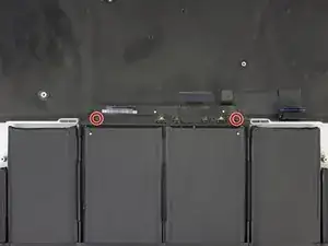
4 don't forget about the two small T 5 screws to the left and right of the battery head board, just below the main battery connector.
5 the Track Pad sits behind the two central batteries. The batteries are adhered to a flat plate that protects the Track Pad which is pretty resilient. You can do the cheese wire trick without cutting through anything you shouldn't. However be careful if you're using a spudger or other tool between the two centre batteries at the top of the T. This is where the Track Pad connector (its very flat and exposed) to the motherboard.
6 seems obvious when it's written , but you will need the adhesive remover if you are interested in removing the adhesive. It's a work out.
Ruairi Kennedy -
I just completed this successfully. The guide was great, and I recommend reading each of the steps’ comments, too. It is possible to cut out a majority of the steps outlined here if you’d rather not dismantle most of your laptop. As I’m a novice and this was the first difficult fix I’d ever tried, the idea of taking so many things apart — including removing the logic board — was a little scary. Everyone calculates risk and reward differently, but for me, the risk of removing the logic board for the reward of being able to remove the battery packs with adhesive remover was too great, so I opted to only do steps 1–4, 42–53 and removed the battery with one of the cards from iFixit’s kit. If you go this route, expect it to be a little frustrating & slow going — it took me around 20–30 minutes of slowly chipping away at the adhesive with only the card. There are other techniques out there (wire, fishing line, etc.) and I’d advise looking into them. Keep track of screws: tape, draw out diagrams, label them, etc.
Jake Thornberry -
I only removed the 10 screws and the back panel, the 5 speaker’s screws (without removing the speakers), and the two battery screws, and managed to remove the battery package without undoing anything else. I used a member card (credit card type) to loosen the adhesives under the batteries.
To remove the rest of the glue, I soaked it with something called Label Off from Biltema (Nordic). Finally, I used methylated spirit (rødsprit) to clean it all up and let it dry for 5 minutes before assembling the new battery pack.
Andreas H. Parlow -
I have now replaced the battery and the dc-in board, and I still can’t get the battery to charge. I also bought a new magsafe power adapter. It appears all cables are connected, and the computer runs fine on the battery (until it runs out of juice, then I will be at a complete loss). No clue what to try next. Any suggestions? Thanks!
matt rogers -
Why do you need to remove the entire logic board??? Seems like if you detach the appropriate cables, remove the speakers, that that should be enough. Removing the entire board doesn’t seem necessary - what am I missing?
Sandwah -
What on earth are you talking about? This has nothing to do with the logic board.
Trevor Picard -
The speaker cables are routed under the logic board, or at least the right-side one is. I found that if you can undo the fastenings on one side of the logic board you MIGHT be able to lever it up and work the speaker wire out without taking the entire thing out.
bobthrollop.redirect -
MacBook Pro 15“ 2014:
if the keyboard is connected nothing works. I disconnected the keyboard and the MacBook was starting automatically. An external usb keyboard is not working either. Is something on the logic board defective or is this failure (usb keyboard not working) because of the disconnected keyboard and the system is confused?
any idea for this?
ps: the battery is loading
Pättes -
MacBook Pro 15” Mid 2012
I had the exact same symptom upon initial completion. The keyboard ribbon is actually 2 pieces on mine. There is a plastic cover sheet (that I tried to use as the ribbon the first time) and then there is the actual ribbon sheet. The keyboard works perfectly now that I have the actual ribbon sheet inserted into the the ZIF connector.
It took entirely too long. I was being very careful. Recovery of the keyboard took me less than an hour. I don’t want to admit how long the original work took me.
I hope you already have yours working. I was very careful due to not having an alternate device for my son to use if the work had failed. The other likely point of failure for the keyboard is damage to the ribbon as it goes under the battery pack. I caught myself almost poking too hard on that spot.
EEM -
You should more clear explain that it is possible to skip the steps 5-35 in the beginning explanation text.
( I lost many time to remove parts and there is also more risk to destroy some connectors ?♂️)
Muescha -
Like many others here, I completed the battery replacement by skipping steps 5-52 and instead removing the battery cells with the “cheese cutter” method. I made my cutter from 20# braided monofilament tied to two 4” wooden dowels (3/8” diameter). I carefully applied 97% isopropyl alcohol to the taut mono with a small artist’s brush. I took my sweet time cutting through the glue, but all in all not too difficult, just tedious. I was super careful and mindful of the fire and explosion hazard, and took necessary precautions. One thing to be careful of using the cheese cutter method is to be sure the mono is is really under the cell package and not just in front of it before sawing away. There are some tight spaces that make this tricky. Once the battery was out I used the iFixit acetone to clean up the glue leftover by carefully applying drops on the strips and letting capillary action take over. After waiting about five minutes, the glue strips could be picked up with the supplied tweezers.
Acme Nerd Games -
Hallo Leute, hab das Akku eben erfolgreich bei meinem MacBook getauscht ohne alles vorher auszubauen. WICHTIG: kein ACETON zum Kleber lösen verwenden! Sonst gehen die Lautsprecher kaputt! Auch kein Orangenpower oder ähnliches! Man nehme sich ein dünnes hochzugfestes Nylonband (oder Zahnseide geht auch) und schneide damit die alten Klebepads sägebandmäßig los.
Also:
In der Hoffnung mich so klar wie möglich auszudrücken war das Folgende meine Vorgehensweise:
1. Deckel ab, Achtung die Schrauben mittig unterm Bildschirm sind kürzer!
2. Akkustecker trennen und vorsichtig umbiegen
3. die 2 Schrauben, die die Batterie in der Nähe des Steckers halten losschrauben
4. nun mit zugfestem Band die Akkus rausschneiden
die im Fix-Kit beigelegten Spatel können dabei unterstützen
die übrigbleibenden Klebereste können einfach mit einem der Plastikwerkzeuge abgemacht werden: erst ein bisschen mit einem Spatel vorarbeiten, sodass man es mit seinen Fingen greifen kann, dann langsam und Richtung weg vom Logikboard vorsichtig abziehen.
Jérôme Achilles -
Was dann noch an Kleberesten übrigbleibt, kann wegen mir auch bleiben. Sonst mit 1-2 Tropfen Lösemittel auf ein Microfasertuch geduldig nach und nach wegwischen. Und Wirklich nur WENIGE TROPFEN verwenden! Sonst gehen die Lautsprecher wohlmöglich kaputt.
5. Mithilfe von Druckluft (2-3 bar! nur) nun sämtlichen Staub vorsichtig rausblasen. VORSICHT: Die Lüfter dürfen sich dabei nicht drehen! Die erzeugen sonst Spannung und grillen wohlmöglich das Logikboard!
6. Neues Akku (Folien dabei vom Akku entfernen) reinsetzen und gleich an die Schraubenlöcher ausrichten.
7. Die 2 Schrauben für die Batterie reinschrauben und mit Gefühl anziehen.
Die packs einzeln auf ihren richtigen Sitz hin prüfen
8. Wenn alles sauber ist und alles richtig sitzt, dann den Batteriestecker wieder auf das Logikboard stecken
9. Deckel drauf. Der Deckel muss von alleine, ohne Schrauben richtig in seiner Ausfräsung liegen. Steht irgendeine Ecke hoch, ist darunter was verkehrt.
Jérôme Achilles -
10. Deckel festschrauben. ACHTUNG: 2 Schrauben sind kürzer auf der Seite des Bildschirms!
Missverständnisse kann ich nicht ausschließen. Darum folgt ihr dieser Anleitung bitte nur auf eigenes Risiko. Ich übernehme keine Haftung für Schäden! Viel Erfolg!
Jérôme Achilles -
Hi guys, just successfully replaced the battery on my MacBook without removing everything first. IMPORTANT: do not use ACETON to loosen the glue! Otherwise, the speakers will be broken! Also no orange power or similar! Take a thin high-tensile nylon tape (or dental floss also works) and cut the old adhesive pads loose. Similarly as with a saw tape.
So:
Hoping to express myself as clearly as possible, the following was my procedure:
1. remove the lid, beware that the screws in the center under the screen are shorter!
2. disconnect the battery connector and carefully bend it over
3. unscrew the 2 screws that hold the battery near the plug
4. now cut out the batteries with tension-proof tape
the spatulas included in the fix-kit can help you to do this
the remaining glue can be easily removed with one of the plastic tools: first work a little bit with a spatula so that you can grip it with your fingers, then slowly and carefully pull it off in a direction away from the logic board.
Jérôme Achilles -
Whatever glue remains can stay because of me. Otherwise, patiently wipe away little by little with 1-2 drops of solvent on a microfiber cloth. And really only use FEW DROPS! Otherwise, the speakers may break.
Now carefully blow out all dust with compressed air (2-3 bar! only). CAUTION: The fans must not rotate! Otherwise, they will generate voltage and possibly fry the logic board!
Insert the new battery ( thereby remove the foils from the battery) and align it to the screw holes. 7.
Screw in the 2 screws for the battery and tighten them with feeling.
Check the packs individually for proper fit
8. if everything is clean and everything fits correctly, put the battery connector back on the logic board.
9. put the lid on. The cover must lie correctly in its groove by itself, without screws. If any corner is sticking up, there is something wrong underneath.
Jérôme Achilles -
10. screw the cover. ATTENTION: 2 screws are shorter on the side of the screen!
I cannot exclude misunderstandings. Therefore, please follow these instructions only at your own risk. I assume no liability for damages! Good luck!
Jérôme Achilles -
Another vote for skipping step 34 after step 4. When I tried to reinstall the new battery, I couldn't get the two step 34 screw holes lined up and still be able to connect the battery cable, so I just left them out. Also, one of the bottom cover screws went AWOL.
I think that anyone with a badly swollen battery can skip to 34 because the battery has already done a lot of the work. I doubt that I used more than a dozen drops of remover, if that. A bit of patience and careful work with dental floss did the trick. Maybe 30-40 minutes to get the old battery out and another 10 to peel off the remaining adhesive.
schendel -
Like most have suggested here, definitely read through all of these comments! I learned valuable tips from other commenters above that made this repair easy. Also like many others here, I opted to skips the majority of steps, and instead focused on steps 1-4, 36-53. When removing the small screws from the back plate, make sure to keep them organized and away from the computer. Because they are slightly magnetic, one of the tiny top middle screws magnetized to the MagSafe charger port my my Mac and I spent 20 minutes thinking it fell on the floor.
I had a nylon thread handy to get some of the packs started. Even with applying the adhesive remover, I found the plastic card iFixit provides was not always strong enough to get the pack started. Cheese cutter method was all it needed to get started!
Make sure to elevate your Mac when applying the remover in whatever direction you want the remover to run. Make sure to test new battery before committing to the new adhesive in case it is faulty!
Good luck!
Patrick King -
At step 9, when reinstalling the io board cable, make sure it is the correct way round as in the photo, it fits the wrong way round as well, which results in the MacBook not starting at all. It took me hours to find my mistake...
Pierre Arnaud -
This is just a suggestion or two to help those that might be doing this for the first time.
1. Separate your screws by the component they came from, i.e. cover screws altogether, fan screws altogether etc. I used PostIt notes turned upside down and put the screws head down to hold them in place and then marked what they were and where they came from.
2. If you have enough work space put the component next to the screws that were removed. Then you have everything located for an easy reinstall.
Steve Rowe -