Einleitung
Werkzeuge
-
-
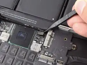
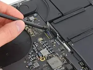
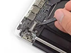
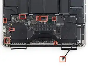
Verwende das flache Ende eines Spudgers, um den linken Lautsprecheranschluss aus seiner Buchse auf dem Logic Board herauszuziehen.
-
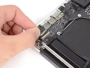
Benutze die Spitze eines Spudgers, um den rechten Lautsprecheranschluss aus seiner Buchse auf dem Logic Board herauszuziehen.
-
-
-
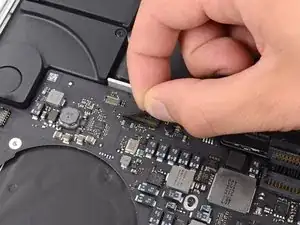
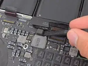
Ziehe das Klebeband ab, das den Stecker des Tastatur-Flachbandkabels abdeckt.
-
Klappe mit dem flachen Ende eines Spudgers die Halteklappe an der ZIF-Buchse des Tastatur-Flachbandkabels nach oben.
-
Verwende das flache Ende eines Spudgers, um das Tastatur-Flachbandkabel aus der Buchse zu ziehen.
-
-
-
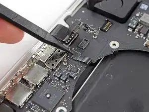
Verwende das flache Ende eines Spudgers, um den Anschluss des Trackpad-Flachbandkabels von seiner Buchse zu hebeln.
-
-
-
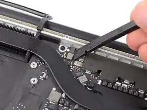
Verwende das flache Ende eines Spudgers, um den Anschluss für die Hintergrundbeleuchtung der Tastatur von seiner Buchse auf dem Logic Board nach oben abzuziehen.
-
-
-
Klappe mit der Spitze eines Spudgers oder mit deinem Fingernagel die Halteklappe an der ZIF-Buchse des Mikrofon-Flachbandkabels nach oben.
-
Ziehe das Mikrofon-Flachbandkabel aus seiner Buchse.
-
-
-
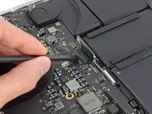
Benutze die Spitze eines Spudgers, um den Verschluss des Display Datenkabels zu lösen und drehe es in Richtung des DC-In.
-
Ziehe das Display Datenkabel aus seiner Buchse auf dem Logic Board heraus.
-
-
-
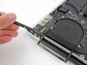
Verwende das flache Ende eines Spudgers, um vorsichtig die Gummikappe der Linsenschraube in der Nähe des MagSafe 2-Steckers abzuhebeln.
-
-
-
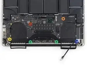
Entferne die folgenden sechs Schrauben, mit denen das Logic Board am oberen Gehäuse befestigt ist:
-
Eine 3,1 mm T5 Torx Schraube
-
Eine 2,5 mm T5 Torx Schraube
-
Eine silberne 5,5 mm T5 Torx Linsenschraube
-
Zwei 5,7 mm T5 Torx Schrauben
-
Eine silberne 3,8 mm T5 Torx Schraube
-
-
-
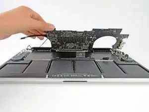
Hebe das Logic Board an der Seite an, die dem Akku am nächsten liegt und drehe es nach oben.
-
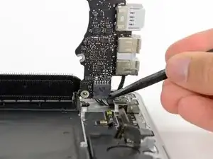
Drücke den MagSafe 2-Stecker vorsichtig mit dem flachen Ende eines Spudgers aus seiner Buchse auf der Unterseite des Logic Boards.
-
-
-
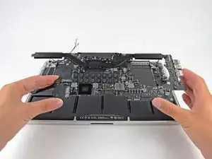
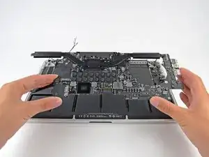
Entferne die Logic Board Einheit vom MacBook Pro.
-
Von oben her im Uhrzeigersinn: Akku, rechter Lautsprecher, Tastaturbeleuchtung, AirPort/Kamera, Display, Mikrofon, linker Lautsprecher, Tastatur und Trackpad.
-
Arbeite die Schritte in umgekehrter Reihenfolge ab, um dein Gerät wieder zusammenzubauen.

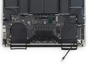
At this point, it should be noted that the author is using two different logic boards through the procedure. Here, for the first time is the difference between a 2.3 GHz board and the 2.6 GHz board. The audio out socket is integral to the 2.3 GHz board. The 2.6 GHz board has a discrete audio out jack that plugs into the logic board. As the disassembly proceeds, the 2.6 board’s audio outlet is unplugged (Step 26/27 pictures note this, but the author doesn’t. So, as I hoped, the 2.3 GHz board can be replaced by a 2.6 GHz board, IF you don’t want an audio out jack!
David White -
Correction. The two boards are NOT compatible. The battery connector and others do not align. A faulty 2.3 GHz logic board is no excuse to get a faster board.
David White -
Note that you should SLIDE not pull these out. Just broke one of them.
andershegelund -
On this model they should be pried straight up from the board as instructed. If your connector looks different from what’s shown in the photos, proceed with caution, verify your model number and make sure you’re following the corresponding guide.
Jeff Suovanen -
I totally missed the pry STRAIGHT UP instruction. I tried to slide one out and it sheared from the board, taking one copper trace with it. Poop!
Peter Kaczkowski -
On MID-2014 Retina, they definitely lift up and out.
MFMauceri -
On LATE-2013 Retina, they definitely lift up and out
KRIS -
This really was helpfully! Thanks!
Jan Dreyer -
VERY HELPFUL. Thank you.
Rafael Pérez -
Yes. This is tricky. Be VERY CAREFUL. I damaged it. I’m afraid this MacBook is RIP.
Richard Cacciato -
This was tricky. I pried up from where the cable enters the connector with a very small flat headed screwdriver - no spudgers to hand!
aaron.sarginson -
I can confirm. you LIFT UP on Mid-2014.
Costantino -
Yes, LIFT UP with 2,3GHz Late 2013
diplomat3000 -
As others have said, this was pretty nerve-wracking to release. I used the pointed end of a spudger and gently pried up on the plastic corner where the wires go into the connector. Not the wires themselves, but the plastic. I wasn’t sure it would work without breaking the connector until it precariously gave way from the board.
justinlyon -
Mid-2015 they lift up
Aaron -