Einleitung
The following guide is a step-by-step process on how to disassemble a Marshall MS-2 Micro Amp Case to gain access to the circuit board, and how to properly remove the circuit board.
Your device may have a damaged circuit board if it smells of smoke, or as if something is burning. Another sign of possible circuit board damage is if the volume, tone, and/ or power knobs do not work. For help with common problems, check the MS-2 Troubleshooting Page.
Circuit boards are important because they serve as the central source for all electronic components within the device. A Marshall MS-2 Micro Amp can be damaged if the amp is exposed to environmental conditions such as heat, dust, or moisture. It can also be damaged a by power overload or surge, or if the device is dropped.
The following guide shows how to turn the Marshall MS-2 Micro Amp off, how to remove its battery, and how to take off the back panel of the amp to access the circuit board. Steps 1-4 are also found in the Disassembling Marshall MS-2 Micro Amp Case Disassembly guide also found here. Steps 5-7 give a description of how to properly remove the volume, tone, and power knobs, and finally how to remove the circuit board itself. Please use caution not to touch any of the wires.
Werkzeuge
-
-
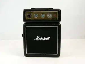
First be sure to turn the power switch to the off position.
-
Do this by turning the leftmost knob counter-clockwise as until the line points to "off."
-
-
-
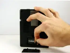
Now remove the battery.
-
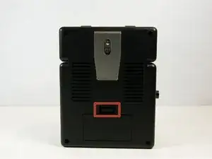
On the back of the device locate the battery cover.
-
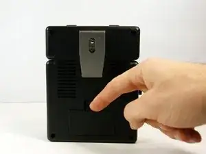
Remove it by pushing down on the clip.
-
Then pull the piece of fabric until the battery comes out.
-
-
-
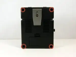
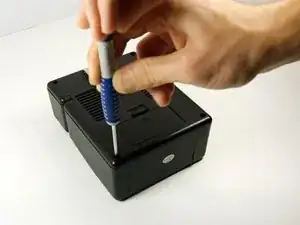
Use the long, skinny phillips head screwdriver to remove the 4 7/16" screws on the back of the device in the four corners.
-
-
-
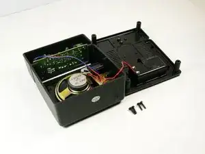
Now pull the back panel off and place it down as shown. Pull the panel straight up so you do not lose the screws.
-
-
-
Remove the volume, tone and power knobs by pulling them straight away from the front of the device. If they do not come off easily use the wedge tool to pry them up.
-
-
-
Use a 10mm socket to remove the nuts from the volume and tone potentiometers.
-
Use a 11mm socket on the power switch nuts.
-
Use a 9/16" socket to remove the nut from the input jack.
-
-
-
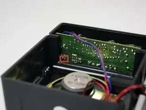
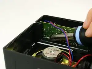
Now you must remove the LED from the circuit board.
-
To do this you will need to use a soldering iron to detach to two pins of the LED from the board. They are the two pins in the lowest leftmost corner of the board.
-
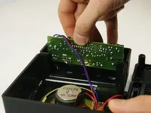
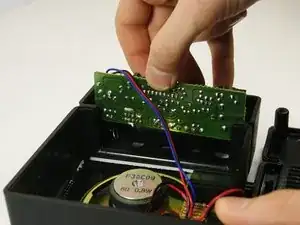
Once detached, pull the board straight up to remove.
-
To reassemble your device, follow these instructions in reverse order.
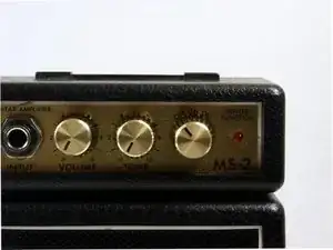
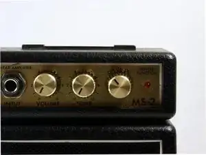
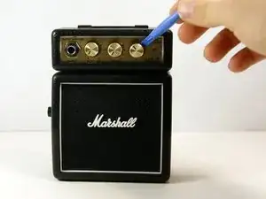
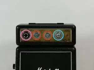
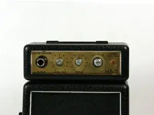
To turn the device off, turn the rightmost knob counterclockwise, not the leftmost one (which controls the volume).
Célestin Taramarcaz -