Einleitung

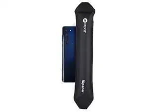
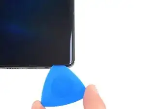
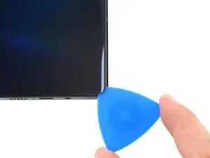
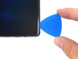
Follow this guide to remove and replace the earpiece speaker on a Motorola Edge.

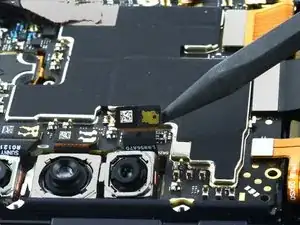
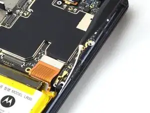
The cameras attached to the motherboard can be removed in any order.

For your safety, discharge the battery below 25% before disassembling your phone. This reduces the risk of fire if the battery is accidentally damaged during the repair. If your battery is swollen, take appropriate precautions.

  1. MGoDXhGpa6KZerSc
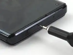
    • Find the SIM tray located at the top of the phone.

  2. 5OnAUy2KyHG2nNZm
    5OnAUy2KyHG2nNZm
    pEPTSEtfMnJetCGA
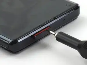
    • Insert a SIM eject tool or SIM eject bit into the small hole in the SIM card tray.

    • If the tool you're using doesn't fit, don't force it. Forcing a tool may cause it to get stuck or break inside the ejection port.

    • Press to eject the tray.

  3. tvD2OkXVvuhl5Z6O
    tvD2OkXVvuhl5Z6O
    CRP4vNjYtqvyNlWR
    cyh2Fgoe1vpD5Yht
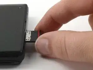
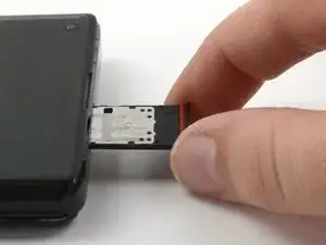
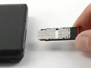
    • Remove the SIM card tray from the phone.

  4. 4FnCQwFMkCAXZ1Bv
    • Completely power off your phone before you begin.

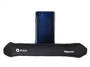
    • Heat an iOpener, then apply it along the bottom edge of the back cover for two minutes.

    • A hair dryer, heat gun, or hot plate may also be used, but be careful not to overheat the phone because the display and internal battery are both susceptible to heat damage.

    I am having no luck removing the back cover on Moto edge. Can apply heat for more than 2 minutes?

    John Wright -

    You may! Heating beyond two minutes won't hurt your device; the iOpener doesn't get hot enough to do that. Apply the iOpener as long and as much as you need to loosen the adhesive.

    Alex Diaz-Kokaisl -

  5. AJvC56xCf3DLgIGM
    AJvC56xCf3DLgIGM
    3HmjeAx2fHi5ho5W
    WZZQ5vre54dPOoYO
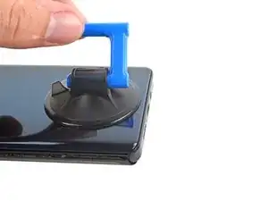
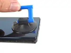
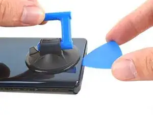
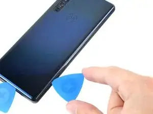
    • Apply a suction cup to the back of the phone, as close to the center of the bottom edge as possible.

    • Pull up on the suction cup with strong, steady force to create a gap between the back cover and the frame.

    • Depending on the age of your phone, this may be difficult. If you're having trouble, apply more heat to the edge and try again.

    • Insert an opening pick into the gap.

  6. 134K3gAaQd61AE2Z
    134K3gAaQd61AE2Z
    qtvhXbE1iNY2tVNU
    M3XV6iS5GGFsQKsh
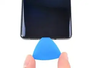
    • Slide the pick back and forth along the bottom edge to slice through the adhesive.

    • Leave the pick in to prevent the adhesive from resealing.

  7. GVKaPvArIykYynBo
    • Apply a heated iOpener to the back cover's right edge for two minutes.

  8. OuSUYlhHlVtqLO2Q
    OuSUYlhHlVtqLO2Q
    cf14Sni2BatKPMPb
    PC2SdtEGWCikGCWS
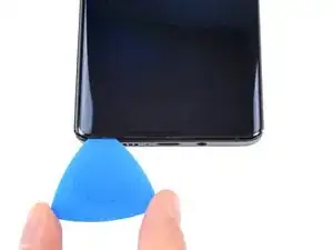
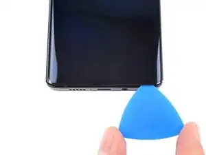
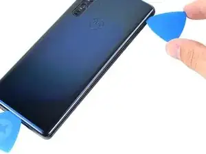
    • Rotate the opening pick around the bottom-right corner of the phone.

  9. yMD46IcUqwFO4tOA
    yMD46IcUqwFO4tOA
    URBcrAgUIiQIcwhA
    dWvkBMaTxV2ih3di
    • Insert a new opening pick into the gap you just created.

    • Slide the pick along the right edge of the phone to separate the adhesive.

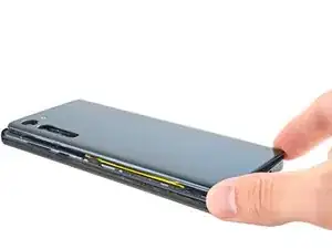
    • Repeat the heating, slicing, and leaving opening picks for the remaining edges of the device.

  10. xUlG23riKM3otWY4
    xUlG23riKM3otWY4
    uRUwx6YfQuPycAkJ
    ecTIFopZkXm5LvDd
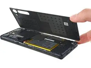
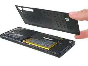
    • Remove the back cover, taking care not to damage the components inside the phone.

  11. pG1yWHHAAqF5LVEW
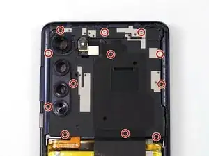
    • Use a T5 Torx screwdriver to remove the twelve 3.4 mm-long screws securing the motherboard cover.

  12. bHMMUrORh42kv6Wp
    bHMMUrORh42kv6Wp
    XCk3QSgRtjhphMkU
    d2VGMAWaZS6F5cqw
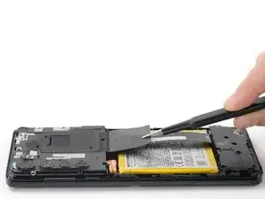
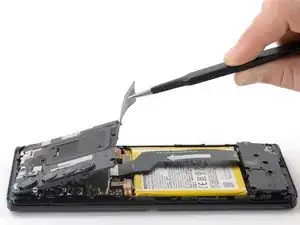
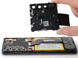
    • Use a pair of blunt tweezers or your fingers to lift up and remove the motherboard cover.

    • The motherboard cover also contains the phone's flash.

  13. 2RGKokBhOhApk3WC
    2RGKokBhOhApk3WC
    GX6WG1MjrXXLZ6bU
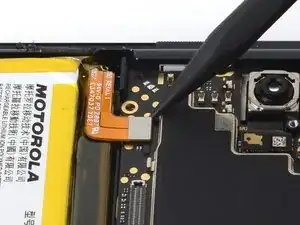
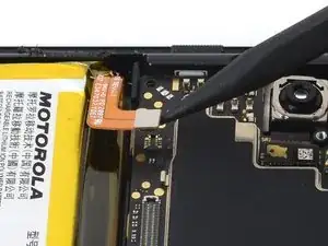
    • Use a spudger to pry up and disconnect the battery cable's press connector from the motherboard.

    • To re-attach press connectors like this one, carefully align and press down on one side until it clicks into place, then repeat on the other side. Don't press down on the middle. If the connector is misaligned, the pins can bend, causing permanent damage.

  14. utJowHPdXuyp6NRc
    utJowHPdXuyp6NRc
    YEDkZCNAjoNjiOvr
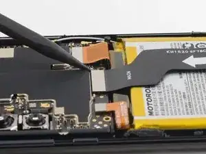
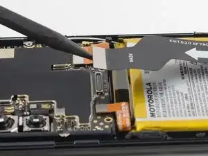
    • Use a spudger to pry up and disconnect the interconnect cable's press connector from the motherboard.

  15. YEPcDHLXc5WrKwYM
    YEPcDHLXc5WrKwYM
    XSE3AcU6Ux4RKxFh
    • Use a spudger to pry up and disconnect the screen ribbon cable's press connector from the motherboard.

  16. BQJw1n3aSqPLAMaK
    BQJw1n3aSqPLAMaK
    HSVYFOrXQKSABVTb
    fKJHXJlJxYfBjcjA
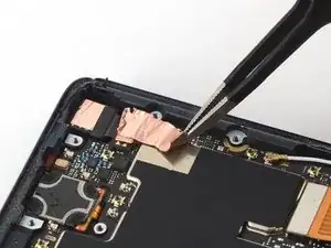
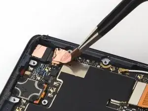
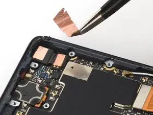
    • Use a pair of blunt tweezers to peel up and remove the copper tape covering the front camera ribbon cable.

    What is the function of the copper tape? Looks in the photo like it was ripped. Can this just be put back in place with no ill effect when reassembling?

    Naka J Ishii -

  17. lWir42SQfMFaLaZg
    lWir42SQfMFaLaZg
    ZaSw1lCtNoobqDi1
    o51if24iiYP2kZBJ
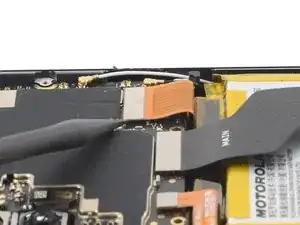
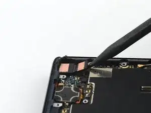
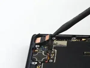
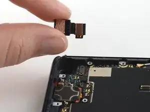
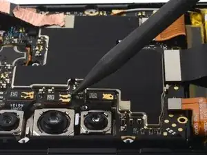
    • Use a spudger to pry up the front camera cable's press connector and disconnect it from the motherboard.

    • Remove the front camera.

  18. AaYCTBIFSWOLQbvt
    AaYCTBIFSWOLQbvt
    AcJDQJuL5uCQpkhR
    BRtWgsTEDGsM2fGM
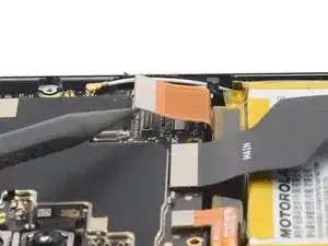
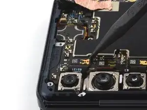
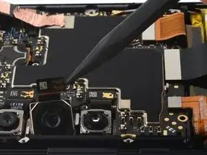
    • Use a spudger to pry up the wide angle camera cable's press connector and disconnect it from the motherboard.

    • Remove the wide angle camera.

  19. WNtJkGtRE3C2OYqn
    WNtJkGtRE3C2OYqn
    eZrRBvgEcAue2Yk2
    PbCw2xGtlBwSauBG
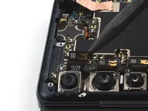
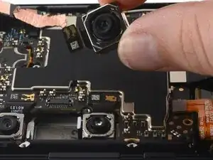
    • Use a spudger to pry up the main camera cable's press connector and disconnect it from the motherboard.

    • Remove the main camera.

  20. 1EpXREyifQhsGoTf
    1EpXREyifQhsGoTf
    S3KmWOSFPIZD6rSq
    OnpkJNdbXixePJJR
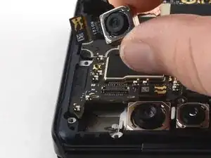
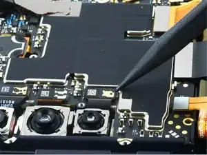
    • Use a spudger to pry up and disconnect the telephoto camera cable's press connector from the motherboard.

    • Remove the telephoto camera.

  21. baFZtXuVewLe4M1W
    baFZtXuVewLe4M1W
    qZIfUCHxiZWAcMoT
    • Use a spudger to pry up the black coaxial cable and detach it from the motherboard.

  22. hHAY5XdPJ52OFKxS
    hHAY5XdPJ52OFKxS
    YYlDoxXJoCWbN2AI
    • Use a spudger to pry up the white coaxial cable and detach it from the motherboard.

  23. gookUPnRhxEDaeuu
    gookUPnRhxEDaeuu
    qlHLgn51IF45SpsF
    BtvnxW3Z6rk4NxOg
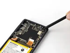
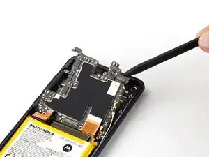
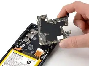
    • Use a spudger to pry up and remove the motherboard.

    • Make sure no cables get trapped under the motherboard during reassembly.

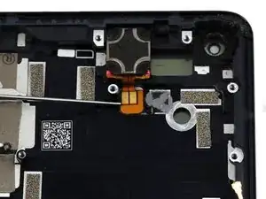
  24. ncOd5rpumTNYHYLL
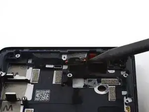
    • Apply a drop or two of isopropyl alcohol to weaken the adhesive securing the earpiece speaker.

    • Wait thirty seconds for the isopropyl alcohol to weaken the adhesive.

    • The adhesive is located both under the ribbon cable and under the earpiece speaker.

  25. FpqpaNQZP1oX1WHH
    FpqpaNQZP1oX1WHH
    jLLkeeDX5xJjlrr1
    jRTHPjvxfcfsUj3O
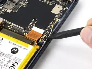
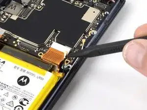
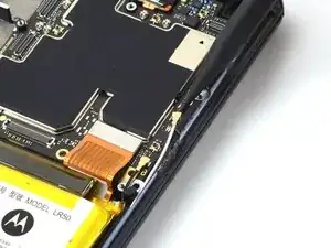
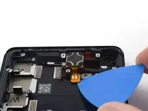
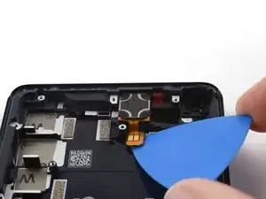
    • Use an opening pick to disconnect the earpiece speaker cable from the midframe.

  26. GoLbG5AeiK3BWyrl
    GoLbG5AeiK3BWyrl
    IjR6hlyFD4IslrWg
    RFRBcyZKURaVwl4r
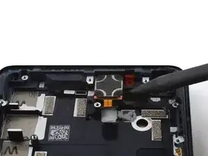
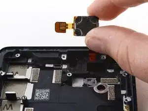
    • Pry at the edge of the earpiece speaker with a spudger to detach it from the frame.

    • If there's any alcohol solution remaining in the phone, carefully wipe it off with a lint-free cloth or allow it to air dry before installing the earpiece speaker.

    • During reassembly, follow this guide if you are using a pre-cut adhesive card to reinstall the earpiece speaker.

Abschluss

To reassemble your device, follow these instructions in reverse order.

For optimal performance, calibrate your newly installed battery after completing this guide.

Take your e-waste to an R2 or e-Stewards certified recycler.

Repair didn’t go as planned? Try some basic troubleshooting, or ask our Answers Community for help.

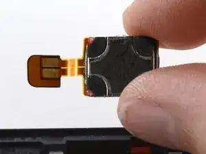
Compare your new replacement part to the original part—you may need to transfer remaining components or remove adhesive backings from the new part before you install it.
Jennifer Berg

Mitglied seit: 21/03/22

2415 Reputation

0 Kommentare