Einleitung

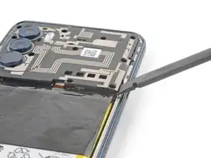
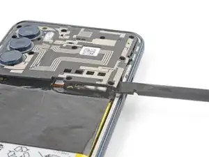
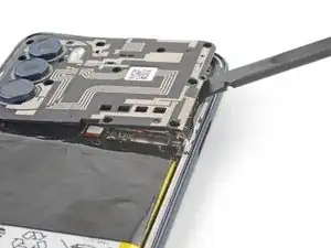
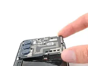
Use this guide to remove and replace the macro camera (upper of three cameras) in your 2022 Motorola Moto G Stylus 5G.

  1. aVaWwFlaFSMr2L6g
    aVaWwFlaFSMr2L6g
    UmKftsVm5vWA1gcl
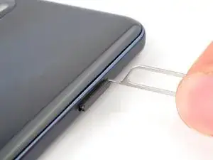
    • Insert a SIM card eject tool or a straightened paperclip into the hole adjacent to the SIM card tray.

    • Press firmly to eject the tray.

  2. dNvGVdJEa2OsT4Oa
    dNvGVdJEa2OsT4Oa
    knQfGPX1xAAj6JJA
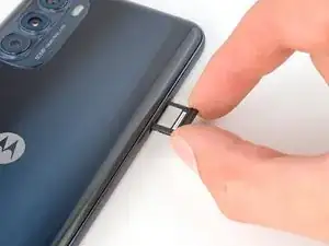
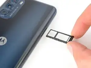
    • Grab and remove the SIM card tray from the phone.

    • When reinserting the SIM card, make sure it's in the proper orientation inside the tray.

  3. T451TmNIVvBcPi2r
    • Discharge your battery to 25% or lower and power off your phone before you begin.

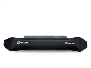
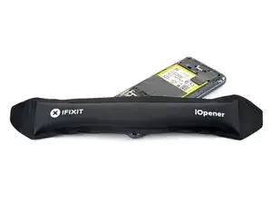
    • Heat an iOpener and apply it to the edge of the back cover with the SIM card slot for two minutes.

    • A hair dryer or heat gun may also be used, but be careful not to overheat the phone—the display and internal battery are both susceptible to heat damage.

  4. oTOFFcYAMFsoEqTH
    oTOFFcYAMFsoEqTH
    Qa6keIrxyjibsLK3
    QIlkPSXhJTrnJGEF
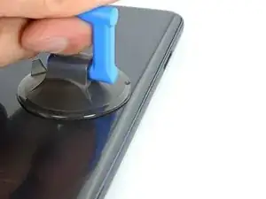
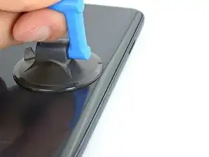
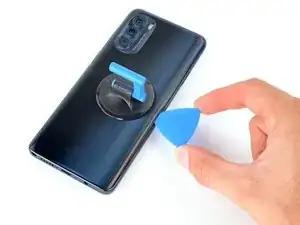
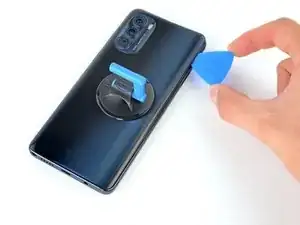
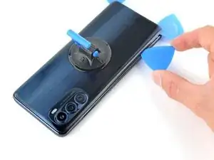
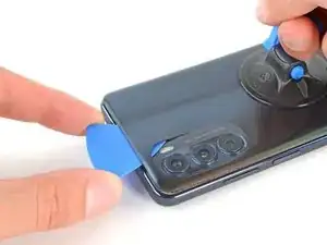
    • Apply a suction cup to the back cover, as close to the center of the right edge as possible.

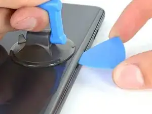
    • Pull up on the suction cup with strong, steady force to create a gap between the cover and the frame.

    • Insert an opening pick into the gap.

  5. 43u2liR4AVwcbD1Y
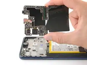
    43u2liR4AVwcbD1Y
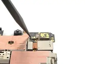
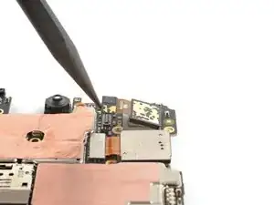
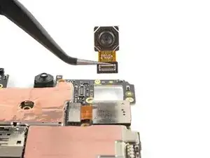
    m1fM5NRUe1rdVChR
    nt5MWA1qhlCSbDFv
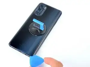
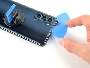
    • Slide your opening pick back and forth along the right edge to slice through the adhesive.

    • Leave the pick in at the bottom right corner to prevent the adhesive from resealing.

  6. j5UZdtBNJqDWbqhf
    j5UZdtBNJqDWbqhf
    kBYodWGbEbVJCSBO
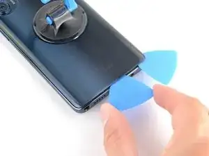
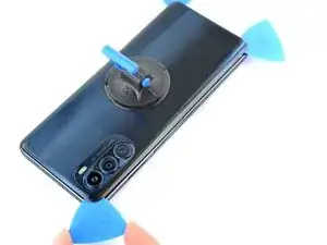
    • Insert a second opening pick into the bottom right corner.

    • Slide this opening pick along the bottom edge to the bottom left corner to slice through the adhesive.

    • Leave the pick inserted to prevent the bottom edge from resealing.

  7. uN266NclgmW6u3ue
    uN266NclgmW6u3ue
    5yE1PvGD6NTrgoSw
    XPoeFM4dFShyfvRT
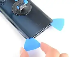
    • Insert a third opening pick into the bottom right corner.

    • Slide this opening pick along the left edge to slice the adhesive.

    • Don't worry about slicing under the camera bezel. It's separate from the back cover and will be removed later.

    • Leave the pick inserted in the top left corner to prevent the left edge from resealing.

  8. OIEFEAxDUXJw4gIy
    OIEFEAxDUXJw4gIy
    H6tdU4dkiHQRE26J
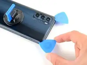
    • Insert a fourth pick into the top left corner.

    • Slide the pick to the top right corner to slice the top adhesive.

  9. CZKlMrxRVgiC3P4L
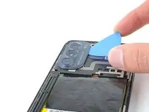
    • Slide an opening pick between the camera bezel and the back cover.

    • The back cover's adhesive is particularly strong around the camera bezel.

    • Slide the opening pick around the camera bezel to separate the back cover from the frame.

  10. 6rYcfrpQYYSMt1oW
    6rYcfrpQYYSMt1oW
    YKkgmBbjVqZdc4sh
    rQPypTYfYivMupX1
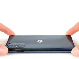
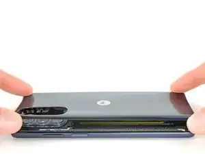
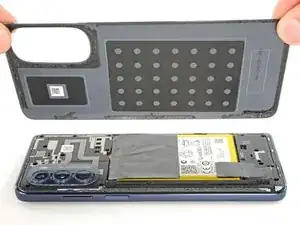
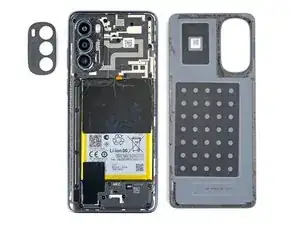
    • Grab and remove the back cover by lifting it away from the phone.

    • If your back cover is still sticking to the frame, slide the pick around the edges of the phone to slice through any remaining adhesive.

    • Reassembly notes:

    • To adhere the back cover with custom-cut adhesives, follow this guide.

    • To adhere the back cover with tape, follow this guide.

  11. K3fEvl55eIQKeliI
    • Heat an iOpener and apply it to the camera bezel for two minutes.

    • A hair dryer or heat gun may also be used, but be careful not to overheat the phone—the display and internal battery are both susceptible to heat damage.

  12. La3kg4vEhtuQSD4k
    La3kg4vEhtuQSD4k
    hH6ryPGaTEeTYfuv
    4Wxsw5tADwLbXYTP
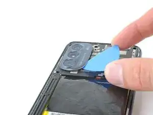
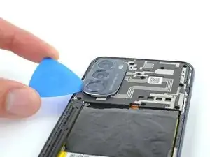
    • Insert an opening pick under the camera bezel.

    • Slide the pick around the perimeter of the bezel to slice the adhesive.

    • If it feels stuck, apply more heat to further loosen the adhesive.

  13. yQ5sCM2voBbbY1h5
    yQ5sCM2voBbbY1h5
    sGAfGcGE4b1XTXEs
    3ZoygEkfaCVbFQDx
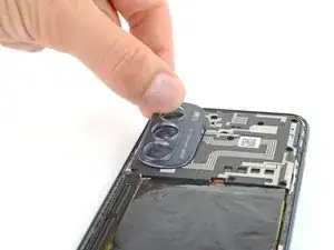
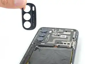
    • Grab and remove the camera bezel.

    • Reassembly notes:

    • This is a good point to test your phone before sealing it up. Follow this guide to perform a hardware test. Be sure to power your phone back down completely before you continue working.

    • To adhere the camera bezel with custom-cut adhesives, follow this guide.

    • To adhere the camera bezel with tape, follow this guide.

  14. U4EW4qTOF2shtKVP
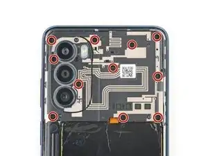
    • Use a Phillips screwdriver to remove the eleven 4.1 mm-long screws securing the motherboard cover.

    • If you can't find all the screws, check under any leftover adhesive residue.

  15. tQUZQCERV5mPnwv6
    tQUZQCERV5mPnwv6
    kyaqv3gXxQVGuaqo
    fdxpGN1lVCnNi3uW
    • Insert a spudger between the bottom right corner of the cover and the frame.

    • Pry up to release the clips securing the cover.

    • Slide the spudger toward the top of the cover and pry to release the right edge.

  16. vJvCGQAK1JSAh25I
    vJvCGQAK1JSAh25I
    oVtFndpOAtRIJoqH
    • Grip the right edge of the cover and pull it off the motherboard.

  17. bPrHggmeuDhav16K
    bPrHggmeuDhav16K
    xABWqy16B1u2J2oa
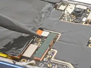
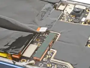
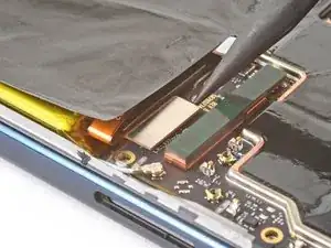
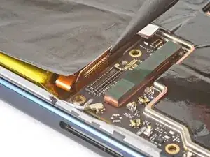
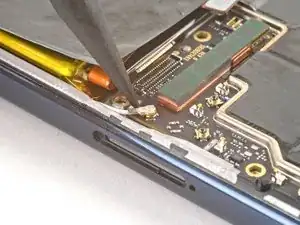
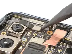
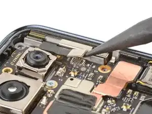
    • Use the point of a spudger to pry up the battery's press connector.

    • When you disconnect connectors like these, be careful not to dislodge the small surface-mounted components surrounding the socket.

    • To re-attach press connectors, carefully align and press down on one side until it clicks into place, then repeat on the other side. Don't press down on the middle. If the connector is misaligned, the pins can bend, causing permanent damage.

  18. EiI6FqEA2OeCvKXw
    EiI6FqEA2OeCvKXw
    bZZlYb6IGlrufctP
    • Use the pointed end of your spudger to pry and disconnect the display's press connector.

  19. gsrQyNsOVXSoUJdI
    gsrQyNsOVXSoUJdI
    MeVyHqNySxDxc5yA
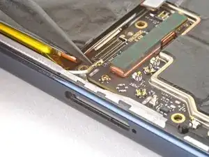
    • Use the pointed end of your spudger to pry and disconnect the white antenna cable.

    • Pry on only the metal head of the connector. Avoid lifting the cable itself as much as possible.

    • During reassembly, these can be tricky to reconnect. Hold the connector in place over its socket and press down with the flat end of a spudger. The connector should snap into place.

  20. W1yoaZ2fMRE1NFiD
    W1yoaZ2fMRE1NFiD
    ZIOHKkSvbXamkyHy
    • Use the pointed end of a spudger to pry up and disconnect the board cable's press connector.

  21. U2cXiGK3WKfxZ1Sb
    U2cXiGK3WKfxZ1Sb
    3lXjJVD2yC1I64ts
    • Use the pointed end of a spudger to pry up and disconnect the 5G mmWave antenna's press connector.

  22. N5yNtlYSYKXeAiJe
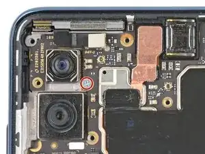
    • Use your Phillips screwdriver to remove the 3 mm-long screw securing the motherboard.

  23. ktfBLUPqNPKhUeBg
    ktfBLUPqNPKhUeBg
    NP125iirXvVuioOf
    l1P5opaRXkNxKqNL
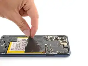
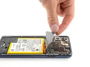
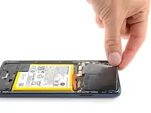
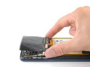
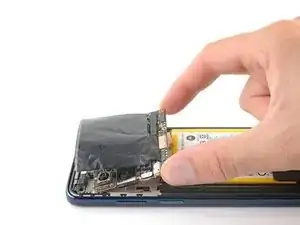
    • Lift and fold the graphite film off the battery and flip it onto the motherboard.

    • Use caution not to tear the film. It's adhered lightly to the battery.

  24. xZc162ROhNH162xj
    xZc162ROhNH162xj
    JK3yFrjU11v2SPPG
    IL4i2vObFMTqjAkQ
    • Grab the motherboard from the bottom edge and lift it from its recess.

    • Be sure the loose cables don't catch on the motherboard as it's removed.

    • During reassembly, make sure no cables or connectors become trapped underneath the motherboard.

  25. WUheWEUjmfMMIuuw
    WUheWEUjmfMMIuuw
    2yWfLZwEYgbIlYSN
    fLP3MIbKPXB4AZq1
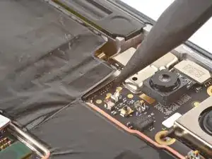
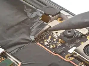
    • Flip the motherboard over so the rear cameras are faced down.

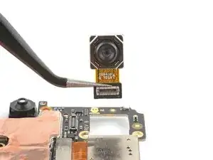
    • Use the point of a spudger to pry and disconnect the macro camera's press connector.

    • The camera may eject from the motherboard. Work slowly to avoid losing it.

    • Use a pair of tweezers or your fingers to grab and remove the camera.

Abschluss

To reassemble your device, follow these instructions in reverse order.

Take your e-waste to an R2 or e-Stewards certified recycler.

Repair didn’t go as planned? Try some basic troubleshooting, or ask our Answers community for help.
Clay Eickemeyer

Mitglied seit: 19/09/22

23447 Reputation

0 Kommentare