Einleitung

  1. rJMvrHInpAY6DDcd
    rJMvrHInpAY6DDcd
    wBODi2ENC2ff3Hts
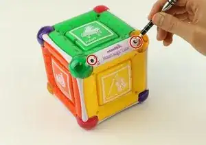
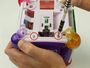
    • Remove two 6 mm Phillips #2 screws on either side of the On/Off Plate.

  2. Sub3qYg2cZJomiZd
    • Remove the On/Off switch plate and save the screws so you can use them later to put the plate back on.

  3. gQSN2DGbBIa1iH3E
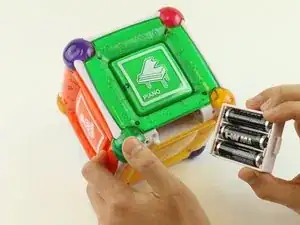
    • Gently pull out the battery cartridge and if needed, replace the batteries with 3 AA alkaline batteries.

  4. eyuttbCQmhEUJbsZ
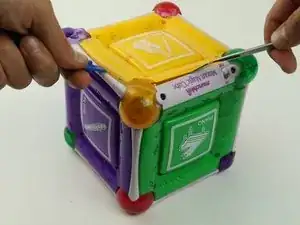
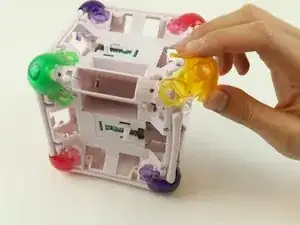
    • Starting with the yellow face, insert the metal spudger between the yellow face and the white frame, prying the frame apart.

    There seems to be no way of doing this without breaking the plastic pegs holding the faceplate in on the first one. I haven't managed to try it yet, but I think to undo the rest of the faceplace without damage, you need *really* long screw driver from which you can reach the opposite faceplate.

    awongawong -

    I absolutely can not get this off. I was able to get one corner to come up, but something broke off inside when it did, now that one corner doesn't seat back in properly. I would like to see a better or updated guide for this as I don't see how I can remove the yellow plate without completely destroying it.

    Roman Sizer -

  5. TjNJGKEDRExN1HFr
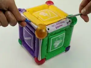
    • Insert the metal spudger in the space created by the plastic opening tool between the frame and face of the cube.

    • Pry the cube face from the frame.

    Could anyone comment the step 5? Because I have no idea how to remove the plate - only one mount was easily unlocked, but the others seems to be fixed by screws.

    Meinst -

    All of the yellow corners are fastened by screws. The only way to remove the yellow panel per the instructions above is to break each corner. I am hoping I can apply epoxy to reassemble.

    mark lester -

  6. WvaaPKbTaGIA1Hgg
    • After removing the square plates, you can unscrew the screws underneath.

    • Remove four 6 mm Phillips #2 screws, located on the sides.

  7. Ux2okVcnKPcaZdl3
    • Remove the rubber corners by simply pulling them off.

  8. bQEAv2oEj5RAKMeO
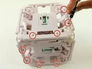
    • Remove twenty-four 6 mm Phillips #2 from all 6 sides.

    • Once the screws are removed, gently pull apart the frame.

  9. RdJtNHdf1hoqqtYH
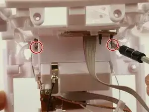
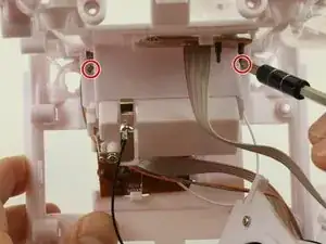
    • Locate frame piece with battery pack and on-off switch, then remove two 6 mm Phillips #2 screws, located on either side of the battery pack.

    • Once removed, the on-off switch will easily slide out of position

  10. uAquCDfLj3aD3Tq6
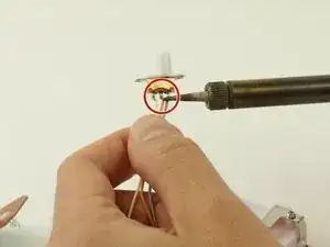
    • To disconnect the on-off switch, carefully desolder the connecting points and remove the switch.

    • Place the new switch into position, and solder back into place.

    • For soldering instructions please see this additional guide Wie man Lötverbindungen herstellt und entlötet

  11. uWLpwBhsnTvH5lVP
    • To reinstall the switch, first place it back into position.

    • Insert the battery pack back into facing the correct way back into int battery pack slot.

    • Lastly, using the Phillips head screw driver to screw the screws back into place.

Abschluss

To reassemble your device, follow these instructions in reverse order.
Panos Valavanis

Mitglied seit: 27/08/15

275 Reputation

0 Kommentare