Einleitung
This guide will take approximately two hours, and involves the use of the iOpener for the adhesive located inside the board to be removed. In addition, all components of this device must be removed before the LCD can actually be removed.
Werkzeuge
Ersatzteile
-
-
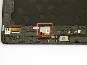
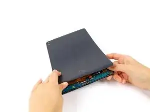
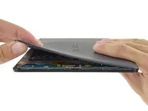
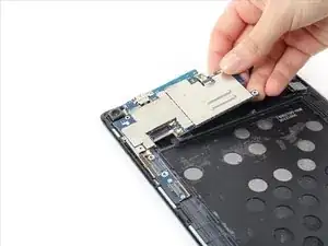
With your fingers, carefully pry off the back plastic casing. Starting at the corners is usually the easiest.
-
-
-
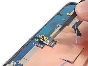
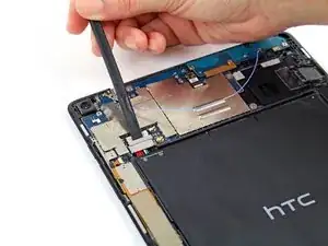
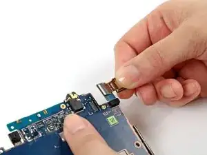
Use a spudger to disconnect the front-facing camera ZIF connector.
-
Use a pair of tweezers to gently lift the front-facing camera up from the motherboard.
-
-
-
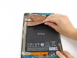
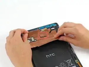
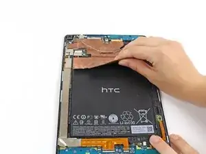
Carefully peel up the copper shielding with your fingers.
-
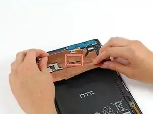
Before fully removing the copper shielding, make sure that the blue antenna cable is out of the way of the copper tab.
-
-
-
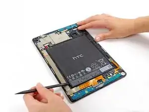
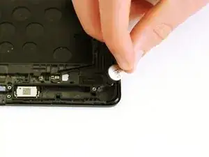
Using the spudger tool, carefully remove the bottom of the battery from it's location below the logic boards.
-
The battery is attached to the motherboard with some adhesive, so you may need an iOpener to loosen up the adhesive. Check out the iOpener guide for info on how to do it.
-
Do not pull the battery from the tablet yet, as it is still connected to the motherboard.
-
-
-
Now remove the metal clip covering the battery's connector cable located above the top left of the battery with the spudger.
-
After the metal clip is wiggled free, the battery's connector cable can be easily removed by just gently tugging it free.
-
-
-
Carefully peel up the copper shielding with your fingers.
-
Before fully removing the copper shielding, make sure that the blue antenna cable is out of the way of the copper tab.
-
-
-
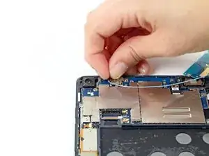
Use your fingers or a pair of tweezers to disconnect the blue antenna cable from the motherboard.
-
The antenna board should now lift free of the motherboard.
-
-
-
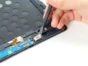
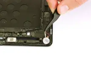
Use a spudger or your fingers to remove the first speaker. The speaker may be heavily glued in and require heat to lift. Be careful as you can pull the speaker apart.
-
-
-
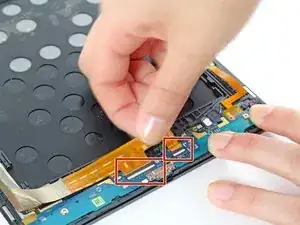
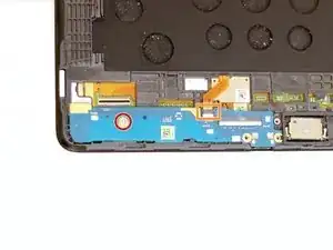
Disconnect the two ZIF connectors attached to the daughterboards.
-
Gently pull on the ribbon cable to remove it.
-
-
-
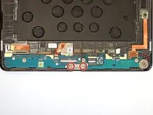
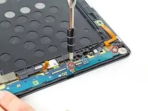
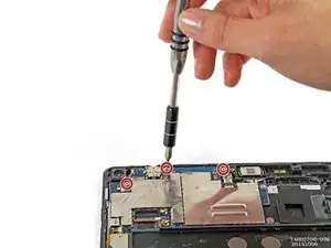
Remove the two 3mm T5 Torx screws securing the metal USB port bracket.
-
Use your fingers or a pair of tweezers to remove the bracket.
-
-
-
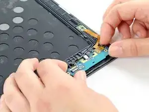
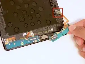
Unscrew the two 3mm T5 Torx screws securing the daughterboard to the device.
-
Use a pair of tweezers to disconnect the vibrator cable. It will lift straight up from the daughterboard connector.
-
Use your fingers to lift the daughterboard upward and out of the device.
-
-
-
The daughterboard has an orange ribbon cable that is adhered to the device. Gently pull the ribbon up and remove the daughtboard.
-
-
-
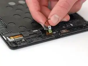
Using your fingers, pull up on ribbon connector to expose another ribbon connector below.
-
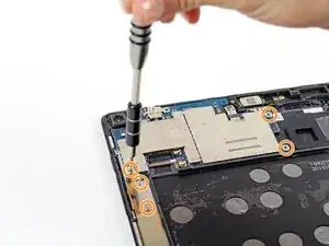
Remove the two 2 mm Phillips #000 screws on top of the second ribbon connector.
-
Pull up the ribbon connector with your fingers.
-
-
-
Refer to the rear-facing camera replacement guide to remove the rear-facing camera from the motherboard and transfer it to the new one.
-
The motherboard remains.
-
-
-
Remove the single 3mm T5 Torx screw.
-
Use a spudger to disconnect the display ribbon cable ZIF connector.
-
Gently lift the USB daughterboard up from the device.
-
-
-
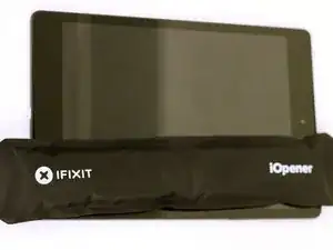
Heat the iOpener for thirty seconds.
-
Throughout the repair procedure, as the iOpener cools, reheat it in the microwave for an additional thirty seconds at a time.
-
-
-
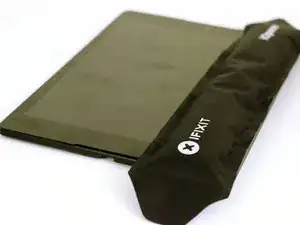
Remove the iOpener from the microwave, holding it by one of the two flat ends to avoid the hot center.
-
-
-
Place the iOpener on the sides of the LCD where the adhesive is located beneath.
-
Let the iOpener sit for at least a minute to soften the adhesive beneath the glass.
-
This should be repeated for every side of the tablet, and each side will most likely need to be heated more than once.
-
-
-
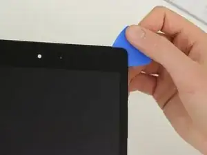
Using the picks located in the iOpener Kit, insert the picks into the corners of the tablet, and move it back and forth along the sides of tablet.
-
Do this for every corner of the tablet until it is possible to pull the LCD from the display assembly with your finger.
-
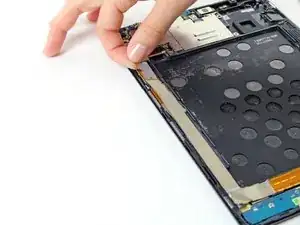
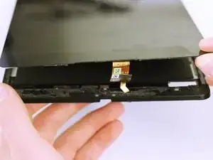
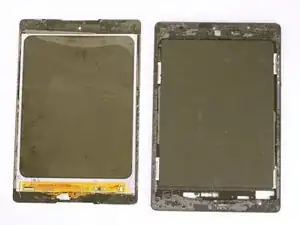
The LCD should come completely free from the back assembly now by just leading the ribbon through the opening in the display assembly.
-
To reassemble your device, follow these instructions in reverse order.
2 Kommentare
What if the glass is broken and the lcd seems fine? Can I just get a new piece of glass and do the heating/pick steps?
Weston S -
So I replaced the lcd abd glass but it won't display any thing when I turn it on I get haptic feedback and the led turns on but nothing on the screen I plugged it in and no battery charging display either I checked yto make sure the screen was not damaged in anyway what could be the problem ? I followed your guied to the letter ???
kanif88 -
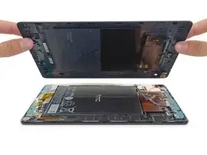


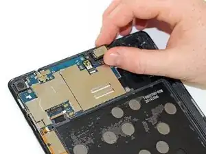



Just removed the cover. On mine, there is a piece of double sided tape, 2"x1", bottom middle, sticking the back cover to the battery. The battery pack's black skin ripped as I pulled the cover off. I was able to peel the skin from the tape and reposition on the batteries. Don't think this black skin is nothing more then a way to print branding and other texts onto the batteries.
Sccoaire -
Same here. Ridiculous!
rexograph143 -
I can confirm that the camera does fit very snugly into back cover.
Start by prying off the cover from the end opposite the camera. When you get near the camera lens, press the lens gently into the body as you continue to release the cover.
Graham Taylor -
Careful pressing that lens into the body, though, because the lens is actually attached to the back cover, not to the camera module (stupid, frankly). It is def a good idea to work from the other corner around, though.
Drew Rushmer -