Einleitung

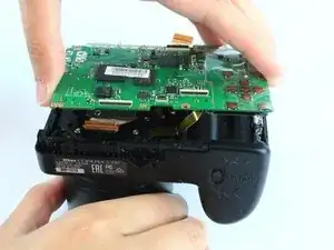
If you encounter issues with your camera motherboard, follow this step by step guide to aid you on replacing it.

  1. mlISKwgu3mjryn6P
    mlISKwgu3mjryn6P
    1JTPlSUGwCV3jDEd
    RudC4ASCMHyGxVEL
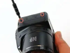
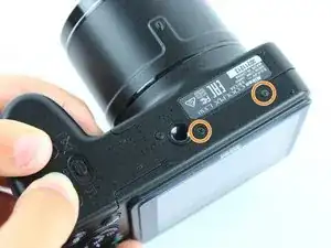
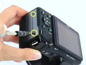
    • There are six screws attaching the back housing to the camera. Remove the screws from the body with a PH000 screw head.

    • Two 1.5x2.5mm screws on the right side.

    • Two 1.5x2.5mm screws on the underside.

    • Two 1.5x2.5mm screw on the left side.

  2. yaW3OYWKDRTxQcUW
    yaW3OYWKDRTxQcUW
    PSDujxKmMkFQBSYo
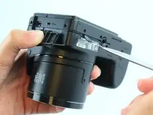
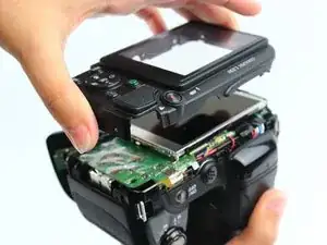
    • After removing the screws, use a metal spudger or plastic opening tool to push the back cover out.

    • The metal spudger can damage the plastic housing, so use caution when applying any pressure to it. Use a plastic opening tool to reduce the risk of damage to the housing.

    • Remove the back housing of the camera by lifting it directly up.

    • The back cover may be slightly tight, therefore more force may be needed to lift it up.

    Note:

    There are 3 locking cam-lugs along the top edge of the back plate. These slot over the top of matching very delicate moulded catches. Carefully lift and lever this top edge first.

    Chris Balchin -

  3. n4PfUV43DA2vm2Lm
    n4PfUV43DA2vm2Lm
    1RPtMJJ5oShvYG5N
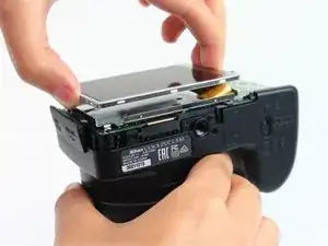
    • Insert the tips of your fingers into the space between the screen and back-plate.

    • Gently lift the screen up and out of the frame.

    • The screen is still held by a flexible display cable, therefore only lift the screen 0.5'' out of the back-plate.

  4. 1KCQIJKTxGFi2HoL
    1KCQIJKTxGFi2HoL
    LnQWT3Nm6TmQpvPd
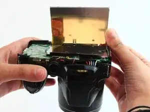
    • Tilt the screen so that the display cable forms a hinge with the backplate.

    • Rotate the display 180 degrees so that it faces you.

  5. mOVAhaVERGGGHnru
    mOVAhaVERGGGHnru
    gfwZEgVdBsgTQRMZ
    Dwu1IIGQCFFsPOBD
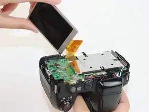
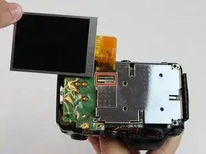
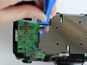
    • The display cable has a ZIF (zero insertion force) connector on the end. This has a tab that has to be pushed out before the cable can be safely removed.

    • Using a plastic opening tool or fingernail, pop up the black clip holding the display cable. This will release the cable.

    • Slide the display cable out of the connector.

    • The display cable can be damaged due to excessive bending, therefore avoid putting unnecessary strain on it.

  6. p6LTJMDEyaxProCn
    • Remove the screws from the silver back-plate with a PH000 screw head.

    • Two 1.5x2.5mm screws on the left side.

    • One 1.5x2.5mm screw on the right side.

  7. rGkabYPoMZBsPrZb
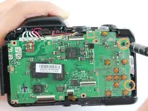
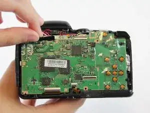
    • The marked red box contains a highly charged capacitor. Check the charge using a voltmeter and discharge it first before continuing. Discharge capacitor guide.

    • Remove the screws holding the motherboard with a PH000 screw head.

    • Two 1.5x2.5mm screws on the right side.

    Err, I don’t think that marked capacitor will hold much charge, though that’s not to say you can’t discharge the flash capacitor as described. The flash capacitor itself will be a large cylindrical component, probably somewhere close by underneath, on the other end of two of those soldered wires.

    Philip Le Riche -

  8. MD3sHDNaPxb4IlQg
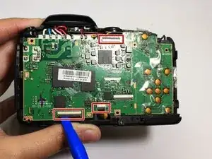
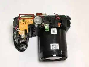
    • Using a plastic opening tool or fingernail, pop up the black clips holding the ribbon cables. This will release the cables.

    • Slide the ribbon cables out of the connectors.

  9. pIVSU4ie5OqsCXNh
    pIVSU4ie5OqsCXNh
    NKeJxUKGVuCf5NEk
    gYCkJNS6FRvoQDC4
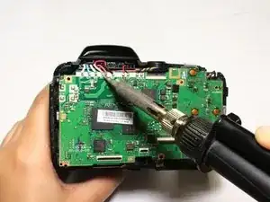
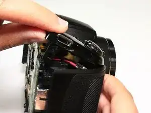
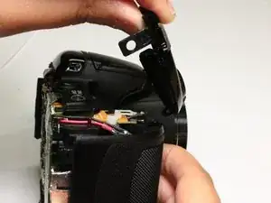
    • Remove the black sticker covering the electrical connections.

    • Desolder the eight wires from the motherboard.

  10. kQoTuWyvMT3DnBVx
    kQoTuWyvMT3DnBVx
    fyAEfQViaiIWKiZO
    oNbRwlXnHOVoALne
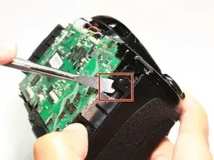
    • Insert a plastic opening tool into the marked position. Push the tool towards the right to release the clip.

    • Using a thumb and forefinger, push the plastic cover up until it is at a 45 degree angle.

    • Pull the cover back and up to release it.

  11. 3MOtjrItplNuDP3R
    3MOtjrItplNuDP3R
    uqLYEsZf6V5h2tBF
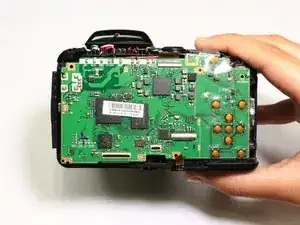
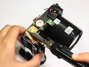
    • The motherboard is still held in place by soldered connections.

    • Carefully desolder the connections .

    • The front cover has been removed in this picture, however the procedure is still the same.

  12. XdWHPdpUQSD6GAve
    • Remove the motherboard by lifting it directly up.

Abschluss

To reassemble your device, follow these instructions in reverse order.
Mohammed Al Rawahi

Mitglied seit: 10/02/16

113 Reputation

0 Kommentare