Einleitung

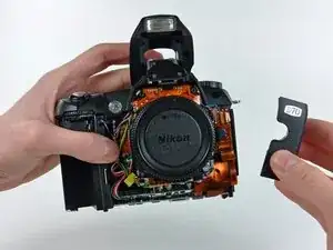
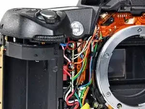
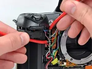
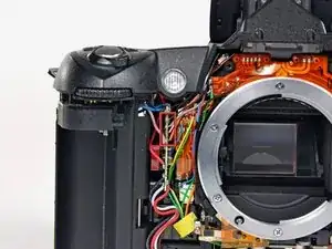
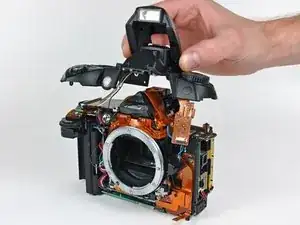
Removing the top cover requires a fine-tipped soldering iron and knowledge of surface mount soldering.

  1. nGyLXbYAyfAxYqVM
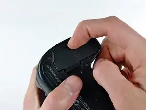
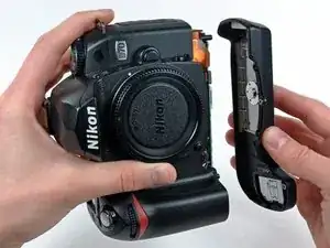
    • Use your finger tip to pull the battery release tab toward the center of the D70.

    • Open the battery door and rotate it away from the bottom cover.

  2. gP1L62ZOQKCETigP
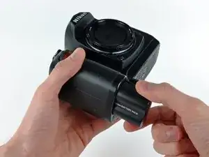
    • Pull the battery out of the D70.

    • It may be necessary to wiggle the battery while pulling to free it from its pocket in the case.

  3. OnWdSq1ef45PHFXB
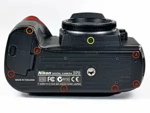
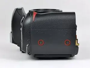
    • Remove the following eight screws securing the bottom cover to the D70:

    • Six 5.8 mm Phillips screws

    • One 10.7 mm Phillips screws

    • One 8.2 mm Phillips screws

  4. lQJ4MJE1bgjaNMlH
    lQJ4MJE1bgjaNMlH
    R4dLwLMcU1p52DrR
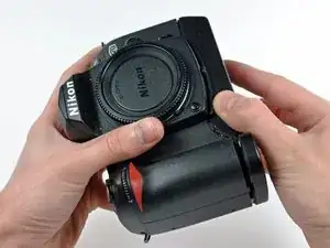
    • Carefully pull the bottom cover to separate it from the body of the D70.

    • Remove the bottom cover from the D70.

  5. r1e5PuGaIhXloVrr
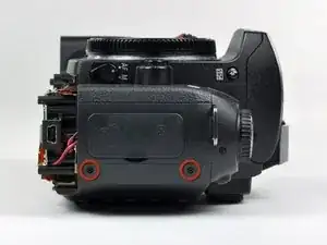
    • Remove the two 4.8 mm Phillips screws securing the battery side of the rear cover to the D70.

  6. y3CG2CXlKiPBUOXd
    • Remove the two 4.8 mm Phillips screws securing the port side of the rear cover to the D70.

  7. QyvbtBNrhmpvNV4n
    QyvbtBNrhmpvNV4n
    iMZNE3iEHhNiYuFm
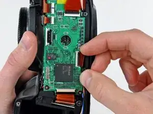
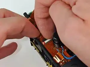
    • Use your fingernail to flip up the ZIF locking flap on the LCD ribbon cable socket.

    • Be sure you are opening the locking tab, not pulling against the socket mounted to the board.

    • Pull the LCD board ribbon cable out of its socket.

  8. SCAjimU2aiLyFVYi
    SCAjimU2aiLyFVYi
    bueQ4q4Ce1SeDNxw
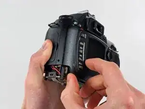
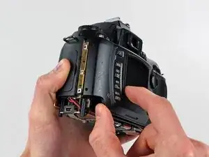
    • Carefully pull the sides of the rear cover away from the body of the D70.

  9. 61CUc3sTwxgAT2AR
    61CUc3sTwxgAT2AR
    dVvSvYmSrKQSpXgV
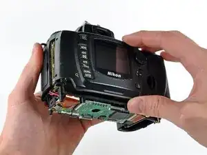
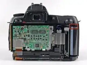
    • Pull the rear cover off the body of the D70, minding the LCD board ribbon cable that may get caught.

    • At this point, the capacitor is visible and its exposed contacts are boxed in red in the second picture. Even though they are recessed, be careful not to touch the contacts to avoid shocking yourself.

  10. OIRKWgDDCaXfNOuC
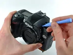
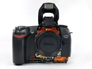
    • Use a plastic opening tool to carefully pry up the flash unit at the point shown in the picture.

  11. XrMwvrKkBNTKLvGK
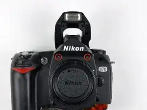
    • Remove the two 4.3 mm Phillips screws securing the top edge of the front cover to the top cover.

  12. EEZR2m6DWPp1PwvG
    • Remove the two 4.3 mm Phillips screws on the face of the front cover.

  13. ev3ru2PBuiujCCIa
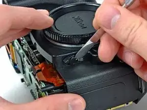
    • Use the sharp end of a metal spudger or a razor blade to peel the sticker out of the center of the automatic/manual focus switch.

  14. Xsm5Z2AkIQwkFjPt
    Xsm5Z2AkIQwkFjPt
    VlDedMRARDC4pVQI
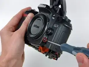
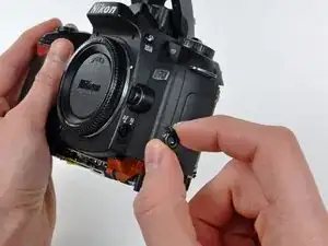
    • Remove the 6.3 mm shouldered Phillips screw from the center of the automatic/manual focus switch.

    • Pull the automatic/manual focus switch away from the front cover.

  15. UH2VJ2q6vH5Lkm5a
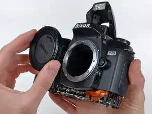
    • If present, remove the plastic cover from the lens mount.

  16. 3dDkvdkDanaPEnZW
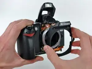
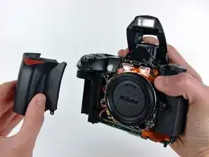
    • Pull the front cover away from the D70.

  17. xX6dgE3ScZrFcBdD
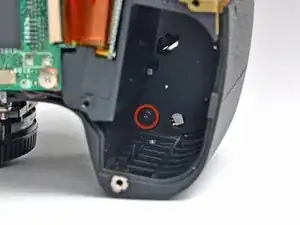
    • Remove the 5.7 mm Phillips screw in the top corner of the battery compartment.

  18. uCgVg4SSmSSmMv5J
    • Remove the 4.2 mm Phillips screw securing the lower edge of the grip to the front of the D70.

  19. IDeRmY3Q6fQ3MyCA
    IDeRmY3Q6fQ3MyCA
    UowMkTElNOEhCsMS
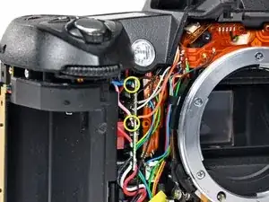
    • Remove the grip from the D70.

    • Do not touch any of the exposed solder points under the grip, as the capacitor is attached in this area. The attachment points for the blue and pink leads of the capacitor are circled in yellow in the second picture.

  20. YnaVaEKDpTAUNn15
    YnaVaEKDpTAUNn15
    qGbtOTZ23TrgUn2N
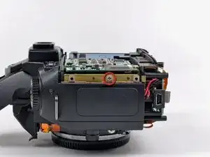
    • Remove the silver Phillips screw securing the port cover to the side of the D70.

    • Remove the port cover from the D70.

  21. kvVFs3m4sLk2rkwL
    kvVFs3m4sLk2rkwL
    SAvKLnMAPqilaJXH
    • Touch the bare leads of a capacitor discharge tool to the pink and blue capacitor leads soldered to the circuit board near the AF lamp.

    • At this point, the capacitor should be discharged. Avoid touching the bare leads to prevent a shock if the capacitor is still partially charged.

  22. WkHnZm63NKPFbmWV
    WkHnZm63NKPFbmWV
    fVU6nlyg5DGxDCWm
    hGYhlMWkrujaqKgX
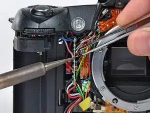
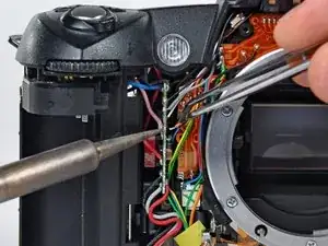
    • Carefully de-solder the black, grey, white, and orange leads (boxed in red) from the side of the circuit board near the AF lamp.

    • Lightly heat the joint of each lead with a soldering iron as you apply slight tension to the wire with a pair of tweezers.

    • Do not excessively heat the board. Also, be sure not to accidentally melt the plastic case with the side of the soldering iron.

    • Repeat the process until all four leads are de-soldered.

  23. wHXLDvZtgyGZPwHl
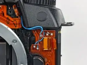
    • In this step, you will de-solder the four wires pictured. Mark the wires with a sharpie or a paint marker to keep track of their locations, as each pair of leads is nearly identical.

    • De-solder the four wires boxed in red using the same procedure on the preceding step.

    • Do not apply too much heat to the joints as you de-solder, as the ribbon cable they are soldered to is extremely delicate and melts easily.

  24. VAqWUP3TInHJ6ics
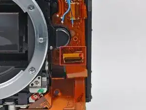
    • If present, remove the piece of tape covering the ribbon cable socket (boxed in red).

  25. MMuUb5NeeoCPcJkB
    MMuUb5NeeoCPcJkB
    QftWq2nv1aXZpQsI
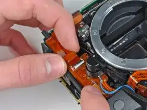
    • Use your fingernail to flip up the ZIF retaining flap.

    • Make sure you are prying up on the ZIF retaining flap, not the socket itself.

    • Pull the ribbon cable straight out of its socket.

  26. CYXlLDRSiQwhHEgJ
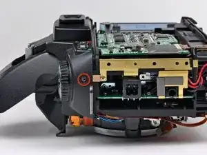
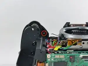
    • Remove the Phillips screw securing the top cover to the D70 near the mode dial.

  27. WFLEClhv3i5B5wPH
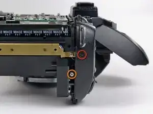
    • Remove the following two screws securing the top cover to the D70 near the shutter button:

    • One black 4.8 mm Phillips screw

    • One silver 4.2 mm Phillips screw

  28. G4WMRIAqnAhxi1qO
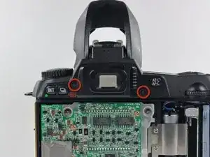
    • Remove the two 7.3 mm Phillips screws securing the top case to the D70 near the eyepiece.

  29. LGsyqFNOftBN6iLO
    • Remove the 4.7 mm Phillips screw from under the top cover near the shutter button.

  30. 4ZUSfCVNjDZUwBYE
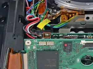
    • De-solder the thin black wire (boxed in red) from the DC/DC board.

    • Do not heat up the DC/DC board too much during the process.

  31. JvqIIEVTEKrZoFvp
    JvqIIEVTEKrZoFvp
    3HBSFVQ2PLLJnyaN
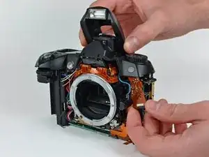
    • Carefully lift the top cover near the mode dial as you pull the mode dial ribbon cable away from the lens base.

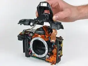
    • Remove the top cover from the D70, minding any cables that may get caught.

Abschluss

To reassemble your device, follow these instructions in reverse order.

Andrew Bookholt

578335 Reputation

Ein Kommentar

Thank you. Andrew your post are so clear I wonder you were hear in India. I'm, having exactly the same camera. It feel down with the lens on it. And since then it didn't work. Y taken to many Nikon center but to no success.

Thanks once again
Sachin Chavre -