Einleitung

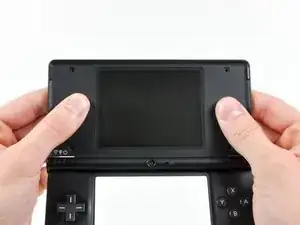
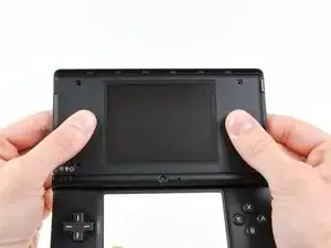
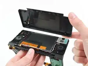
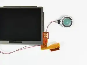
This guide will walk you through replacing the upper LCD on your DSi.

  1. xvUu2VHXnLOaoxyD
    xvUu2VHXnLOaoxyD
    GJgBKkUY2j6UrTTr
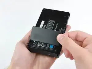
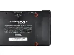
    • Unscrew the two Phillips screws securing the battery cover to the lower case.

    • The screws remain captive to the battery cover.

    • Grasp the battery cover and lift out of the lower case.

  2. TMGAeGDWRXJKjqkf
    TMGAeGDWRXJKjqkf
    pXTJP3k1hRhVckSv
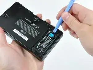
    • Wedge the edge of a spudger in between the top of the battery and its lower case housing and pry upwards to dislodge the battery.

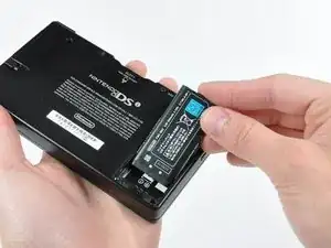
    • Grasp the battery and remove it from the DSi.

  3. ZElvjs4G5DRnVKEX
    ZElvjs4G5DRnVKEX
    NNd3fYSswNeKCoBU
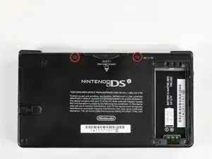
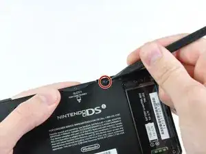
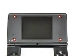
    • Two screws are hidden underneath two rubber feet highlighted in red.

    • Use the tip of a spudger to pry the rubber feet out of the lower case.

    One of the feet did break on me, tweezers came in handy for picking it out

    Willie Narvaez -

    I unfolded and sharpened a paperclip. You can use that to stab and hook the rubber without tearing it, as the rubber is thick enough to reseal when reinserted.

    Keegan Andersen -

    Nasty, broke my spudger and the feet in this step.

    TimedIn -

  4. MPpnnO22qoYDH1YH
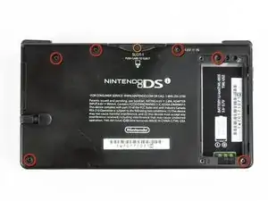
    • Remove the following screws securing the lower case to the body of the DSi:

    • Six 5.2 mm Phillips #00 screws.

    • One 2.7 mm Phillips #00 screw.

    Impossible d'enlever les vises… trop serré! comment faire?

    evrobert03 -

    i can't get the screw by the gamecard slot out, PH#00 is too small and PH#0 is too big

    Iblowup -

    same problem here. maybe try a JIS?

    darth mango -

  5. MqTKErbDcomH6eMJ
    MqTKErbDcomH6eMJ
    HuePUMK6TciCQZEj
    OkwvvvtBbd53ugBG
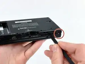
    • Insert the spudger in between the lower casing and lower panel near the top right corner of the DSi.

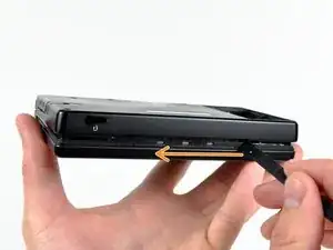
    • Carefully run the spudger along the edge of the outer casing, creating an opening between the body and the casing.

    • Continue running the spudger around the body of the DSi until the majority of the lower case has been separated.

  6. ZsX1F2YxXpOFEtuH
    ZsX1F2YxXpOFEtuH
    BS25HSFVrSclu2X1
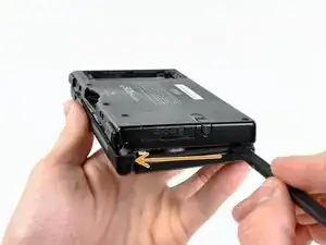
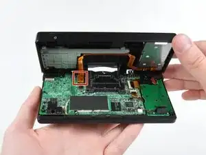
    • Carefully lift the lower casing from its bottom edge.

    • The lower case is still attached to the motherboard by the volume and SD board cable highlighted in red. Do not try to completely remove the lower case of the DSi yet.

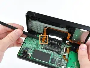
    • Pry the volume and SD board cable up from its socket on the motherboard using a spudger.

    • Once the cable is completely removed, then you may take off the entire outer casing.

  7. kmVh26fubSE4TiMD
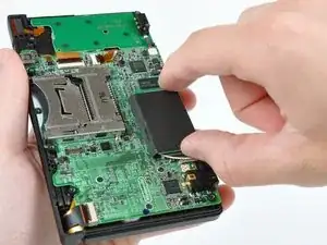
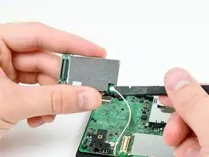
    • Pull the Wi-Fi board away from the motherboard by its edge closest to the headphone jack.

  8. QDhsgwruDwxGZhwa
    • Pry the Wi-Fi antenna connector straight up from its socket on the Wi-Fi board.

    After reassembling it, I switched my Nintendo DSi xl On and only the blue power light, is on after that it doesn't respond any more, except while charging it blinks

    Phillips -

  9. rOrYJByq3ETfmbdk
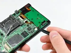
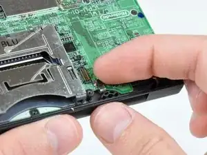
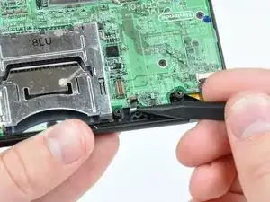
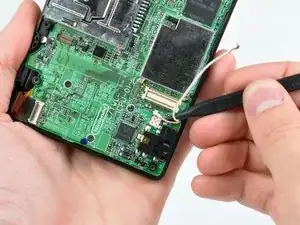
    • Use the tip of a spudger to pry the power board connector out of its socket on the motherboard.

    do not pry up! pull to one side so you don't disconnect the clip from the motherboard!

    Lisa -

    Actually Lisa, you are incorrect. If you pull to one side you WILL end up pulling the connector off the motherboard. It is designed so that you ARE MEANT TO pry it upwards out of the connector. All you need to do is use the point or corner of the flat edge of a spudger (or a small flat-headed screwdriver), push it ever so slightly under the middle of the small white plug where there is a small recess in the connector for just this purpose. Prying the plug up in this fashion you should clear the connector with the spudger by prying it up through the recess rather than catching the connector and pulling it off the board.

    James Gravestock -

    how to fix if the clip comes off of the motherboard?? please help!

    jaime -

    Push it back in straight if it is still in one piece.

    Tman Tech -

    If the socket comes off the motherboard along with the connector, what’s the best way to fix it?

    Kimberly Meyer -

    it has to be soldered back on, so if you can't do it yourself, find someone who can (maybe a local repair shop).

    just some mango -

  10. GkLxSBWqXUZvEWfO
    GkLxSBWqXUZvEWfO
    wH65BTmxHuvJEaw3
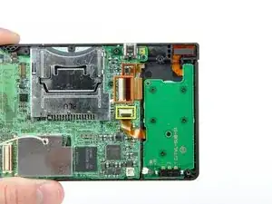
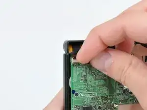
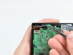
    • Use your fingernail or the edge of a plastic opening tool to flip up the retaining flap on the following three ZIF sockets:

    • Lower touchscreen cable

    • Lower LCD cable

    • Power board cable

    • Be sure you are prying up on the hinged retaining flaps, not the sockets themselves.

    • After flipping up the locking tabs on all three sockets, use your fingers or a pair of tweezers to gently pull the cables straight out of their sockets.

    I accidentally broke the retaining flap off of the lower touchscreen’s socket. Is it possible to reattach it?

    Thewolfpack23x -

    Mine broke off too. At first I thought it would just pop back in, but when I looked at it under magnification, I can see that a tiny piece of plastic actually snapped off the flap. I think we're farked. Looks like the only way to fix would be to solder on a new cable connector.

    trevorsklar -

  11. QQ53GOjQUAjipiLR
    QQ53GOjQUAjipiLR
    RnDBPQTsLn1a4m5E
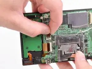
    • Use your fingernail or the edge of a plastic opening tool to carefully flip up the touchscreen ribbon cable retaining flap.

    • Make sure you are flipping up the retaining flap, not the socket itself.

    • Use the tip of a spudger to pull the touchscreen ribbon cable straight out of its socket.

    When I was putting mine back together, the flap popped off and when I tried to put it on with a tweezers, it snapped. Any suggestions other than scrap it or use it without the touchscreen? Pictures at https://sites.google.com/site/memesbyluc...

    Lucas Hoekstra (Lucas9810) -

    This little flap is a pain in the butt to get back in! If there is any way to bypass the removal of this, my advise is to do it!

    Tamara Girodie -

    Adding on: The cable actually ended up breaking as the tweezers I used to put it back in scraped part of the gold ribbon off. Be extremely careful!!!

    Tamara Girodie -

  12. mafsk2s4efjqS2NP
    mafsk2s4efjqS2NP
    A6utw32KgXdGX3hn
    • Use your fingernail or the edge of a plastic opening tool to carefully flip up the dual camera ribbon cable retaining flap.

    • Make sure you are flipping up the retaining flap, not the socket itself.

    • Use the tip of a spudger to pull the dual camera ribbon cable straight out of its socket.

  13. 4JjISgpwCH2gWOm4
    • With the tip of a spudger, Pry the microphone antenna up off its socket on the motherboard.

  14. n3Z4aW2J3yJGnHfM
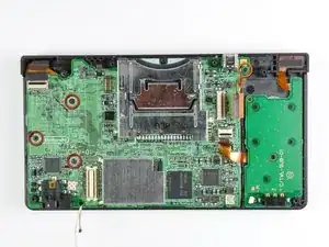
    • Remove the following four Phillips screws securing the motherboard to the DSi framework.

    • Three longer screws.

    • One short screw.

    • Pull the microphone and Wi-Fi antenna cables out of the notch cut into the motherboard near the headphone jack.

  15. B2aHLlOTl2dIdMJP
    B2aHLlOTl2dIdMJP
    tQHEhIuY2yBQBFvm
    oexSRl3VTauw5BVp
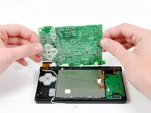
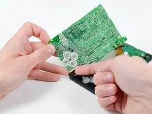
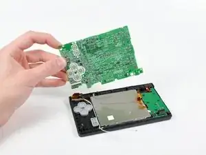
    • Slightly lift the motherboard upwards to reveal the upper LCD ribbon cable above the ABXY buttons .

    • Use your fingernail or the edge of a plastic opening tool to carefully flip up the upper LCD ribbon cable retaining flap.

    • Make sure you are flipping up the retaining flap, not the socket itself.

    • Remove the motherboard from the DSi.

    I actually chose to leave this ribbon cable connected, and had no issues completing the rest of the steps around this. Just be careful not to pull the cable!

    Tamara Girodie -

  16. OrGPD1EqHlD4RNKS
    OrGPD1EqHlD4RNKS
    i2kPqfain3lsgpdh
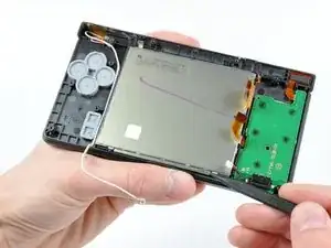
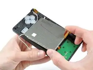
    • Use the tip of a spudger to pry the metal backing of the lower LCD up from the DSi's framework.

    • Lift the lower LCD assembly out of the DSi.

    It’s not mentioned here, but I found it easiest to just remove the buttons and rubber backings here as well - they will likely just fall out anyway when moving the case around and you may lose them.

    Tplan -

  17. XtJs1jId5EAvcIRC
    XtJs1jId5EAvcIRC
    WmVIDsyWEKlHBpVh
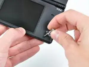
    • Use a pushpin to remove the four plastic screw covers on the front bezel.

    Is there a good way to get these out without damaging them? Using a push pin or exacto-knife usually still damages them some.

    Or can you get replacements?

    Tplan -

  18. wueAlMGxSrLL3EJS
    • Remove the four Phillips screws securing the rear bezel to the front bezel.

  19. oqAGP5feCZKlaC5E
    oqAGP5feCZKlaC5E
    uikqqBwWuF2PtMJe
    hxQAeMcF3P6UwgZr
    • Using two hands, gently slide the rear bezel upwards.

    • The rear bezel will move only about 2 mm.

    • Slightly close the case of the DSi and lift the rear bezel straight up out of the DSi.

  20. Fp4KetPQt1n4Asjk
    Fp4KetPQt1n4Asjk
    XrpMWJWkXJH5Bgkm
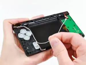
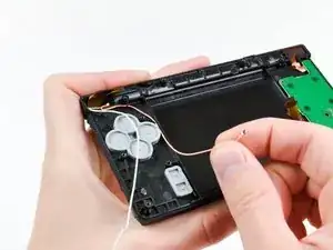
    • Continue de-routing the microphone and Wi-Fi antenna cables through the opening located on the bottom DSi's framework.

    Same as above:

    I found it easiest to just remove the buttons and rubber backings here as well - they will likely just fall out anyway when moving the case around and you may lose them.

    Tplan -

  21. sWAbcVkrPbQMxICD
    sWAbcVkrPbQMxICD
    GNextcRc2LZjopQU
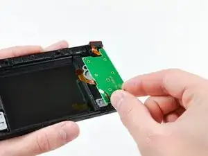
    • Remove the five Phillips screws securing the power board to the DSi's framework.

    • Lift and remove the power board from the DSi.

  22. GgHLWiIGLafMQtJi
    GgHLWiIGLafMQtJi
    OTqpoNV4CoyAjI1Y
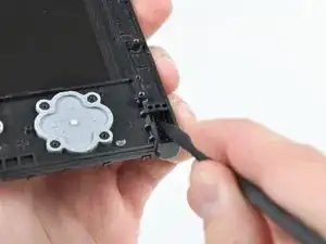
    • Push the metal hinge pin inward on the D-pad side of the front lower panel with the tip of a spudger.

    • The pin should move about 3 mm and stop. It is not necessary to try to completely remove the pin.

  23. GvmpoYBrc1RYKQn4
    GvmpoYBrc1RYKQn4
    eH4MT34L5puBXKDx
    UrhoMM3dAVaNKvhY
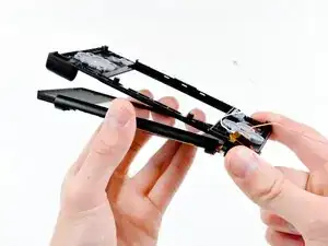
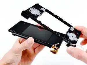
    • Slightly detach the lower and upper halves of the DSi.

    • Do not completely separate both halves yet. There are several ribbon cables that remain threaded through both panels.

    • De-route the upper LCD and dual camera ribbon cables through the slit near the ABXY side of the front lower panel.

    • Separate the lower and upper halves from each other.

  24. GtIgIUABKYpIHoQp
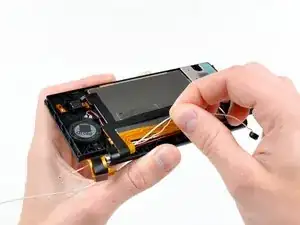
    • Using your fingers, grasp the microphone cable and de-route it through the hinge.

    • The microphone will likely pop out of its housing, so it is probably easier to completely remove it at this point.

    • De-route the Wi-Fi cable through the hinge.

  25. a2d6uURpFYdKNI2m
    a2d6uURpFYdKNI2m
    BVkYYvalDGCcVIXp
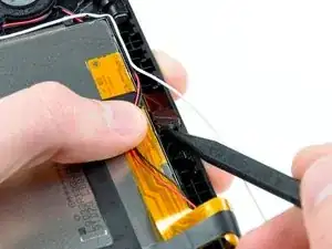
    • Tightly coil the display and dual camera ribbon cables enough to push them through the steel hinge tube.

    • Remove the steel hinge tube.

    • Carefully push both coiled ribbon cables through the tube molded into the front upper panel.

    When reversing this after putting the new screen in, the larger of these two ribbon cables will be built into the new screen.

    I found it easiest to spend some time coiling the new ribbon cable from the middle up to the end, similar to how the old screen’s ribbon cable is coiled.

    This makes moving it back through the molded tube in the housing and then slipping the steel hinge tube a lot easier.

    Surprisingly, these cables are pretty sturdy - I’ve kinked one or two and it still functions, however I’d still say take it slow and try to avoid anything like that.

    Tplan -

  26. mKMGeg2VpPDVxWPC
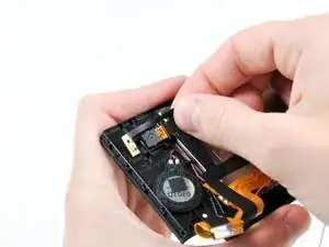
    • Pry the front-facing camera straight up out of its housing in the front bezel.

  27. cGF2k3K1mSGXgBN4
    cGF2k3K1mSGXgBN4
    Yx4RJqy5XTeEsSGR
    • Lift the rear-facing camera out of its housing in the front bezel.

    • Remove the dual camera cable assembly from the DSi.

  28. HeXSagXh6bVoVndD
    HeXSagXh6bVoVndD
    GKE4qNhOuG6DEQmH
    • De-route the Wi-Fi antenna cable from its channel in the front bezel.

    • Lift the Wi-Fi antenna board straight up and remove it from the DSi.

  29. t2vohEMZoBKtSo63
    t2vohEMZoBKtSo63
    HCkBULxTNVRCJMmt
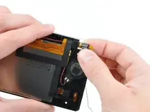
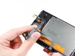
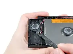
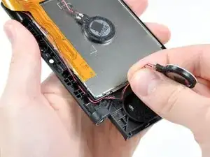
    • Use the flat end of a spudger to pry the right speaker straight up and out of its housing in the front upper panel.

    • Lift the right speaker and set it on top of the upper LCD.

  30. DCu1WYZxcFiQublL
    DCu1WYZxcFiQublL
    6SXJc3uKUgKrUZyv
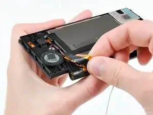
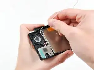
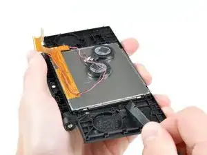
    • In the same manner as previously described, remove the left speaker.

    • De-route the left speaker cables from underneath the upper LCD.

    • Lay the left speaker on top of the upper LCD.

  31. OIsEFn1qCBJFUCfO
    OIsEFn1qCBJFUCfO
    XOymFId65gMnGKqX
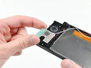
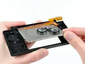
    • Cautiously wedge the flat end of spudger underneath the upper LCD.

    • Loosen the adhesive by running the spudger along the perimeter of the upper LCD.

    • Lift the upper LCD by its upper right corner and remove it from the front upper panel.

  32. y1ScPIdrvK13PdSE
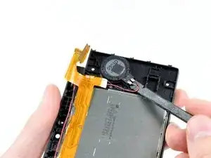
    • Desolder the speakers from the upper LCD by heating up the solder joints with a soldering iron and simultaneously using a pair of tweezers to pull the speaker wires away from the logic board.

    • If you have never soldered before, we have a guide that makes it easy.

    On step 10: I accidentally pried up the "Power Board Cable." (Be sure you are prying up on the hinged retaining flaps, not the sockets themselves.) Is there an easy way to make it reconnect? I can't get it to stay back on mother board. I've attempting to get my DSI repaired, but many local stores and including manufacture Nintendo aren't offering assistance so I figured I'd fix it myself. Please assist if you can.

    Mayor LiteFoot -

Abschluss

To reassemble your device, follow these instructions in reverse order.

Walter Galan

685541 Reputation

12 Kommentare

The tricky part is getting the upper screen and black ribbon through the hinge. I found that curling them and pushing them through a drinking straw that was cut short first and then pushing the straw through the hinge hole made it a whole lot easier.

Damian -

So true. I just broke my second ribbon cable while replacing the case. While most repairs on the dsi are relatively easy, this ribbon cable makes any repairs that involve it a nightmare.

Brendan Smith -

I curled the larger (new) cable the same way the smaller one was already curled. Just spend some time doing that until it was shaped that way and it was a lot easier to get both through the molded tube and ring.

Tplan -

I used this guide for change the cover broken by my son.

Thank you

Bompa (Italy)

Bompa -

While doing this I accident messed something up. When I power on the DSi, the bottom screen just flashes and the DS turns off. What did I do wrong?

Ruben Colon -

I think you broke the ribbon cable, it also happened to me, sadly the ribbon cable is soldered into the top screen so you need to buy a new top screen

Rubio Mejia -

make sure you plugged in the screen correctly, it's a bit fiddly because of how there's another cable overlaid on top of it, but both need to be properly seated otherwise you won't get a boot

Kaleb White -

Hey guys, i have two problems....

I have ordered a replacement housing for my daughter, so i hat to completely and fully disassemble everything.

Now I put it back together and first off, i have two strange square washer left AND, the upper screen turns on fine, the lower too.. but after 1 second, the upper screen gets all strange... colors are wrong.. I close the Lid, open it up and again, 1 second perfect, after that it turns discolored...

Any idea where the two washer could come from as i cant find them in the Description here and also what could be wrong with the display now?

Caylean Koar -

Why do you need to disassemble your DSi on the bottom? Why is that important on every DS/3DS console? I would never do something with "Very difficult" tasks.

Santi12008 -

Great guide.

it was hard, i ripped the broken lcd flat cable and it was hard to put the new one through the hinge, but i did it.

Then, when putting everything back together, i broke the sd card flat cable, %#*@ you manufacturer.. why such a flimsy cable with strong glue to the case?

be careful, the sd card connector is hard to reconnect and when you try to release it from the case, it may break

Ciro Monteiro -

"Just do it backwards" is NOT helpful reassembly instructions because the hinge doesn't work that way. To "do it backwards" would be somehow sucking it in via the area above the dpad which is physically impossible. In order to reinsert the hinge, you need to get all the ribbon cables threaded through and the wires on the other side, before putting the top front plate back on, then slide the hinge piece into the top inner shell from the outside until it is flush with the hole it goes into. Then line back up the bottom inner plate, and push it "out" towards the place the LEDs will be, from the gap below the top LCD. I had to look up a separate video of someone doing this, and I'm afraid that in trying to figure it out myself using this guide I might have deformed the hinge somehow because I cannot for the life of me get it to go back where it needs to go.

jcryay -

Your last comment is what I am literally struggling with right now. I cannot get the hinge to go back where it needs to go.

Mayor LiteFoot -