Einleitung

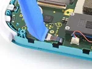
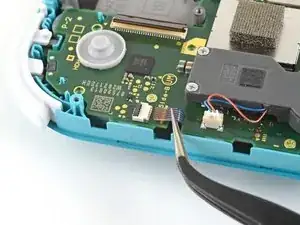
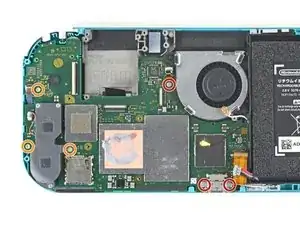
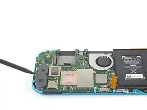
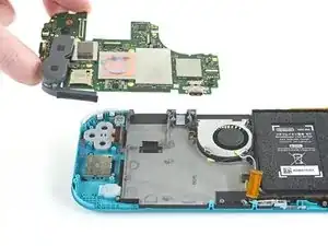
Diese Anleitung zeigt, wie der rechte Joystick in der Nintendo Switch Lite ausgebaut und getauscht werden kann. Mit einem neuen Joystick kann das lästige "Joy -Con-Driftproblem" gelöst werden. (Um den linken Joystick auszutauschen folge dieser Anleitung).

In der Switch Lite sind JIS-Schrauben verbaut, zur Not passen aber auch Bits für Kreuzschlitzschrauben. Sei aber sehr vorsichtig und beschädige die Schraubenköpfe nicht. Die Bits von iFixit können auch für JIS-Schrauben verwendet werden.

Hinweis: Das Abschirmblech und der Kühlkörper müssen dabei ausgebaut werden. Die alte Wärmeleitpaste muss von beiden Bauteilen - und der CPU - entfernt und neue aufgetragen werden, bevor sie wieder eingebaut werden können.

  1. CtSXh5SNdBfY3d4X
    • Bevor du die Reparatur beginnst, musst du das Gerät komplett ausschalten.

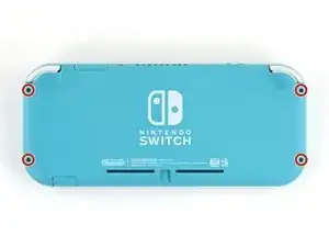
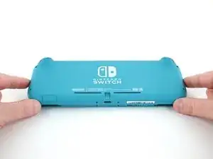
    • Entferne die vier 6,3 mm Y00 Schrauben, mit denen die Rückseite befestigt ist.

    • Halte während der ganzen Reparatur die Schrauben gut geordnet und achte darauf, dass jede Schraube wieder an ihren alten Platz kommt.

    All my screws got stripped any ideas on how to remove?

    Almost A Mammal -

    A Y0 screwdriver seemed to work better for me.

    Tommy Morrill -

    What type of screw driver do I use to un screw the screws and which way

    Luca Capito -

  2. LoododBfWX565CM3
    LoododBfWX565CM3
    axePI5XqFET5KVdd
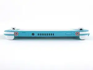
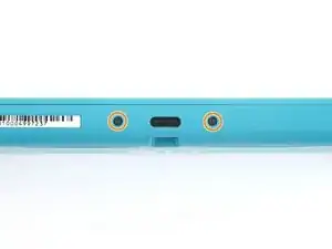
    • Nimm einen JIS 000 Schraubendreher/Bit oder ein Original PH000 Bit von iFixit und entferne folgende JIS-Schrauben, mit denen die Rückseite oben und unten befestigt ist:

    • Zwei 3,6 mm lange Kreuzschlitzschrauben an der Oberkante des Gerätes

    • Zwei 3,6 mm lange Kreuzschlitzschrauben an der Unterkante des Gerätes

    • Passe auf, dass die Schraubenköpfe nicht rundgedreht werden. Drücke das Werkzeug fest nach unten und arbeite langsam. Wenn die Schrauben nicht herauskommt, dann versuchen es mit einem anderen Bit.

  3. OdqFPXbVWUcLdDot
    OdqFPXbVWUcLdDot
    CIVhMktLorQQTIDM
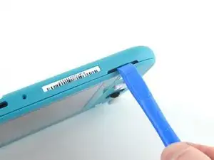
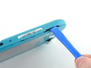
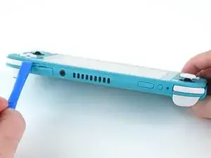
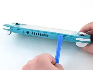
    • Setze ein Öffnungswerkzeug in die linke Öffnung für den Lautsprecher an der Unterseite des Geräts ein.

    • Verdrehe das Werkzeug, so dass sich die Rasten lösen, mit denen die Rückseite befestigt ist.

    • Setze das Öffnungswerkzeug nicht tiefer als nötig ein, du könntest sonst das Lautsprechermodul beschädigen.

  4. wrE1q1yNyF2ogBV4
    wrE1q1yNyF2ogBV4
    Pmw5QYCTejXbIUKw
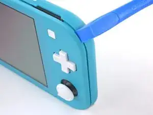
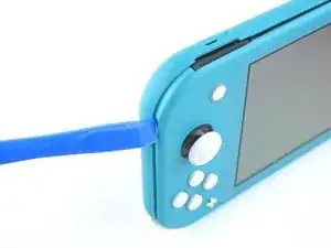
    • Schiebe das Öffnungswerkzeug um die untere linke Ecke herum, so dass sich die Rasten auf der linken Seite des Geräts lösen.

  5. RlPaVdXmyVJlvRdR
    RlPaVdXmyVJlvRdR
    xpNFcLWpxIZGYAZo
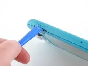
    • Setze ein Öffnungswerkzeug in die rechte Öffnung für den Lautsprecher an der Unterseite des Geräts ein.

    • Verdrehe das Werkzeug, so dass sich die Rasten lösen, mit denen die Rückseite befestigt ist.

    • Setze das Öffnungswerkzeug nicht tiefer als nötig ein, du könntest sonst das Lautsprechermodul beschädigen.

  6. nKd22DZNmOtktjJ6
    nKd22DZNmOtktjJ6
    ZFI5WyJ26AuYMJ34
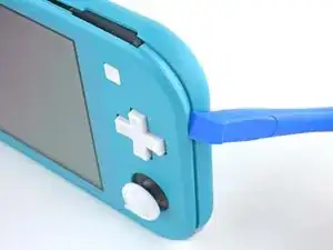
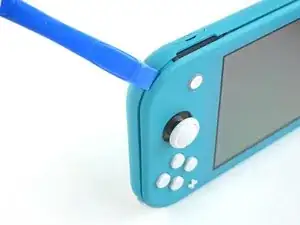
    • Schiebe das Öffnungswerkzeug um die untere rechte Ecke herum, so dass sich die Rasten auf der rechten Seite des Geräts lösen.

  7. UB4MQPADBNC3AKGp
    UB4MQPADBNC3AKGp
    FDjmileJQ6nKxeRT
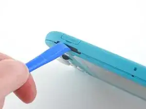
    • Schiebe das Werkzeug weiter am Spalt an der Oberseite des Geräts entlang und heble die Rasten auf.

  8. 3YVyXRJqMpDtXeYv
    3YVyXRJqMpDtXeYv
    N5JkogvdUb1o4kID
    ZH5AGwN3bXMGGKnl
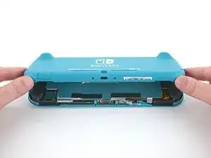
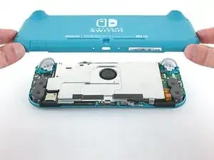
    • Hebe die Unterkante der Rückseite an und klappe sie wie ein Buch auf.

    • Entferne die Rückseite.

  9. vsR2tYTiCfHGSlh1
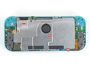
    • Nimm einen JIS 000 Schraubendreher/Bit oder ein Original PH000 Bit von iFixit und entferne folgende vier JIS-Schrauben:

    • drei 3,1 mm Schrauben

    • eine 4,5 mm Schraube

    There are four screws instead of three mentioned

    Khurram Chaudry -

    it doesnt mention 3 anywhere, and it labels all four

    Ezi -

    With how easy it seems to be to do serious damage with the next few steps, I figured I'd say that realistically you can skip steps 9-13 when doing this repair. While they provide a bit of extra security by disconnecting the battery, the left stick is completely accessible and replaceable without touching the heat shield or anything underneath (And steps 17 and 18 disconnect power from the daughter board regardless).

    Nate -

  10. FIwGjkfOhVmFCyvp
    FIwGjkfOhVmFCyvp
    LUwt2Ov3TDBmbBMy
    CxSr6WAFIqTkPknC
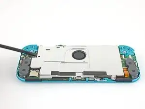
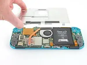
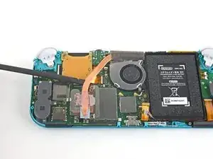
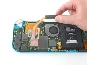
    • Hebe mit dem Finger oder einem Spudger das Abschirmblech hoch und entferne es aus dem Gerät.

    • Wahrscheinlich spürst du etwas Widerstand. Das ist normal, weil das Abschirmblech wegen der Wärmeleitpaste ein wenig am Kühlkörper hängen bleibt.

    • Entferne das Abschirmblech.

    • Reinige das Abschirmblech mit Isopropylalkohol und einem Mikrofasertuch von der Wärmeleitpaste. Bringe vor dem Zusammenbau neue Wärmeleitpaste am Kühlkörper an.

    You may need to replace the thermal paste on the heat sink.

    ahoz28 -

  11. NfJ4EyXkJrCSjyMP
    NfJ4EyXkJrCSjyMP
    SWRCDlfTfCNLuWJO
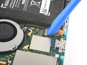
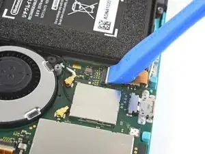
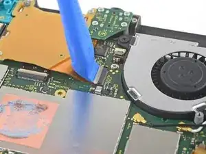
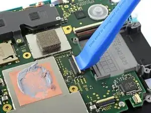
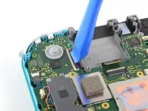
    • Klappe den kleinen, scharnierartigen Sicherungsbügel am ZIF-Verbinder des Verbindungskabels auf der Hauptplatine mit dem Fingernagel oder einem Öffnungswerkzeug hoch.

  12. EOLi3GutoqJNvstI
    EOLi3GutoqJNvstI
    hO2FmA16pHiJq2to
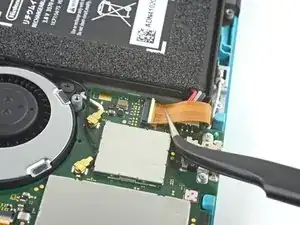
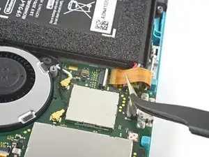
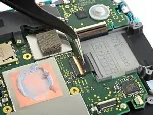
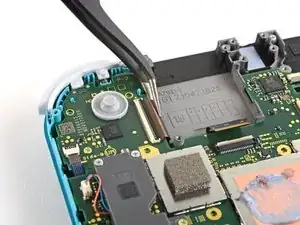
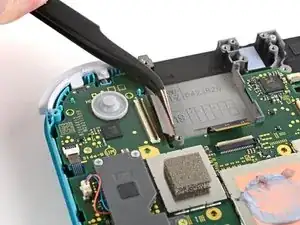
    • Schiebe das Verbindungskabel mit Hilfe einer Pinzette aus dem Anschluss auf der Hauptplatine heraus.

    I turned the unit off beforehand, I used tweezers just like the instructions said (ifixit branded) , my device sparked and now it won’t turn back on

    User Service -

    The flap came off is it important or is there a way t fix it?

    Jose Cruz R Rangel Cordero -

    We're you able to get it working without the white flap? My screen is not working after putting it back together and i noticed this white flap was falling off

    Jimmy “Ghost” Trost -

  13. yfTkAmQeCWGhAEl2
    yfTkAmQeCWGhAEl2
    SFobIivmPhWAmdMb
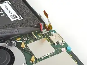
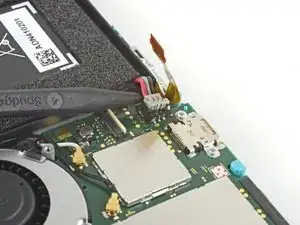
    • Heble den Akkuanschluss mit der Spudgerspitze gerade nach oben aus seinem Anschluss auf der Hauptplatine heraus.

    Caution the connector may not be properly soldered onto the motherboard. For me it snapped off the pins and now have to find a place to get that fixed if even possible. may have bricked it.

    Craig Osman -

    Yup, broke the connector right off the motherboard. Thanks, ifixit -_-

    Justin Kerr -

    I backed out when I reached this point. I couldn't risk damaging it. Do u just need to pull it up? Did you mean that it might have been soldered shut below?

    Jannalyzer -

    You should just need to pull straight up, but make sure you’re pulling on the wires or the gray plug—do not pull on the black socket or it can snap off of the motherboard.

    Adam O'Camb -

    I pulled straight up from the south side on under 2 or three wires and held down the device as I pulled and the gray connector disconnected from the black connector on the Switch. Just be careful at this part.

    Jon -

    With how easy it seems to be to do serious damage at this point, I figured I'd say that realistically you can skip steps 9-13 when doing this repair. While they provide a bit of extra security by disconnecting the battery, the left stick is completely accessible and replaceable without touching the heat shield or anything underneath (And steps 17 and 18 disconnect power from the daughter board regardless).

    Nate -

  14. iuutsxvMo3TxGutF
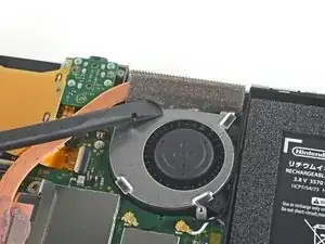
    • Entferne den leicht verklebten Schaumstoff am Lüfter mit dem flachen Ende eines Spudgers oder mit deinem Finger.

    • Der Schaumstoff muss nur soweit abgezogen werden, dass der Lüfter freiliegt.

    When reassembling, the foam may fold down between the fan and heatsink, blocking airflow. Gently lift the foam back up on top of the fan. The adhesive film should hold the foam together.

    Kean Stump -

    Is removing the heat sink absolutely necessary?

    Clark Aulden -

    It’s not necessary, but it makes it much easier to remove and replace the game card reader, since the heat sink partially covers the connector.

    Craig Lloyd -

    Not really…….. I never remove it. It slides out quite easily once disconnected.

    Alan Sears -

    What do you do if these screws are stripped? They strip easily

    Whatever -

  15. QWMQ2YrSy4JCPv4E
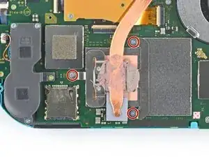
    • Nimm einen JIS 000 Schraubendreher/Bit oder ein Original PH000 Bit von iFixit und entferne die drei 3 mm JIS Schrauben, mit denen der Kühlkörper an der Hauptplatine befestigt ist.

  16. 4x22rRB1EQtWewRL
    4x22rRB1EQtWewRL
    jBHwjFqQxbHLBpjV
    bXVdT31XEDGyDS5L
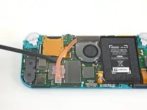
    • Hebe den Kühlkörper mit dem Finger oder einem Spudger von der Hauptplatine hoch und entferne ihn.

    • Möglicherweise verspürst du etwas Widerstand. Das ist normal, da der Kühlkörper leicht mit Wärmeleitpaste mit der CPU verklebt ist.

    • Reinige den Kühlkörper und die CPU mit Isopropylalkohol und einem Mikrofasertuch von der Wärmeleitpaste. Trage vor dem Zusammenbau neue Wärmeleitpaste auf der CPU auf.

    16.5 remove cartridge / headphones jack……….

    Calvin Martin -

    I've read that there are different ways to apply thermal paste, which should I use?

    Kai B -

    My kit did not come with thermal paste..

    Bryan Donovan -

  17. TedQdrMIGlD5s2Cs
    TedQdrMIGlD5s2Cs
    iV5IFW6AXF4xQsAZ
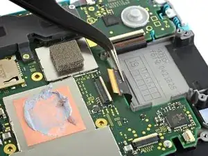
    • Klappe den kleinen, scharnierartigen Sicherungsbügel am ZIF-Verbinder des Kabels zum Game Card Leser mit dem Fingernagel oder einem Öffnungswerkzeug hoch.

  18. 6DhSgR2bkKKHYvWB
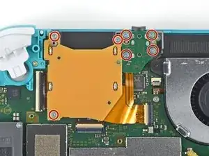
    • Nimm einen JIS 000 Schraubendreher/Bit oder ein Original PH000 Bit von iFixit und entferne die sieben 3,1 mm JIS-Schrauben, mit denen der Game Card Leser und die Kopfhörerbuchse befestigt sind.

  19. C31EaHZUrBYXyVbx
    C31EaHZUrBYXyVbx
    OllZknAglBNcYDEl
    fdvAGth5QQYsx3K5
    • Bewege den Game Card Leser mit einer Pinzette oder deinen Fingern nach links, so dass das Kabel aus seinem Anschluss herausgleitet.

    • Entferne den Game Card Leser und die Kopfhörerbuchse.

  20. KrXqYGqKyhavqmAm
    • Nimm einen JIS 000 Schraubendreher/Bit oder ein Original PH000 Bit von iFixit und entferne die beiden 4,5 mm JIS-Schrauben, mit denen die Baugruppe der rechten Trigger-Taste an der Hauptplatine befestigt ist.

    I think a whole step to remove the game card reader and speaker jack was skipped here…

    ConfusedAzn Random -

    yes, just found that sadly these comments do not show unless we click on the , which is unhelpful

    Micheal speed -

    also, you need to remove the left trigger button

    Micheal speed -

  21. 5lu12BIJX1YVqAn2
    5lu12BIJX1YVqAn2
    JqP15TQm6YEPY2LD
    • Entferne die Baugruppe der rechten Trigger-Taste.

  22. chqnDc31GYFROsZw
    chqnDc31GYFROsZw
    xiBauSfiZNTfHMTR
    • Wenn das Gummipad nicht an der rechten Trigger-Taste hängen geblieben ist, dann hole es jetzt mit einer Pinzette oder den Fingern heraus.

  23. xcOWWVkaeBgFKHal
    xcOWWVkaeBgFKHal
    24CeDyxGrpjSn1Za
    1lPMeSKxkRAeXsx5
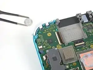
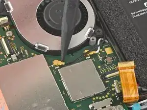
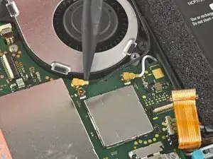
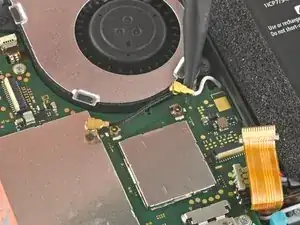
    • Heble das schwarze Antennenkabel mit der Spudgerspitze gerade nach oben aus dem Anschluss auf der Hauptplatine hoch.

    • Wiederhole das Ganze für das weiße Antennenkabel.

  24. GoxOWhyctZE5h3Vb
    • Klappe den kleinen, scharnierartigen Sicherungsbügel am ZIF-Verbinder des Lüfterkabels mit einem Öffnungswerkzeug oder dem Fingernagel auf.

  25. lyZ4AOAU4AZl5tqe
    lyZ4AOAU4AZl5tqe
    wRLrI3jwCANoNyju
    • Schiebe das Lüfterkabel mit einer Pinzette aus seinem Anschluss auf der Hauptplatine heraus.

    There’s a step missing after this to remove the screws that hold the orange game cartridge slot. Those 7 screws have to be undone and the ribbon unclipped first before moving on to the next step.

    Heather Thrasher -

  26. FfuwxRxZSkQcVKpi
    FfuwxRxZSkQcVKpi
    4gU2dcBdLmKxWPjo
    • Klappe den kleinen, scharnierartigen Sicherungsbügel am ZIF-Verbinder des Displaykabels mit einem Öffnungswerkzeug oder dem Fingernagel auf.

    skipped a step or two about removing the golden piece in the photo above, and the other little board

    Eddy Whitaker -

    If I broke the clasp on the ZIF connector can I elec tape it down?

    kevin miller -

  27. wSwylFJAsZW3NgsI
    wSwylFJAsZW3NgsI
    OeV561fN4xH1AcgI
    • Schiebe das Displaykabel mit einer Pinzette aus seinem Anschluss auf der Hauptplatine heraus.

  28. FWkJe1DNdTPNxfFc
    FWkJe1DNdTPNxfFc
    MgI1qpopQRiC1Coj
    • Klappe den kleinen, scharnierartigen Sicherungsbügel am ZIF-Verbinder des Touchscreenkabels mit einem Öffnungswerkzeug oder dem Fingernagel auf.

    Can I electrical tape this down if I broke the clasp?

    kevin miller -

  29. Tp6mukLD3ybSYZfq
    Tp6mukLD3ybSYZfq
    ATK1pvPvge36251G
    • Schiebe das Touchscreenkabel mit einer Pinzette aus seinem Anschluss auf der Hauptplatine heraus.

  30. SxMDga2Qvmmjn5Ar
    SxMDga2Qvmmjn5Ar
    GFUX4uIGXPqnyGqf
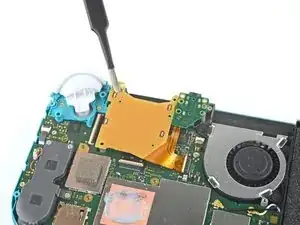
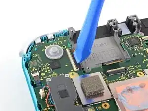
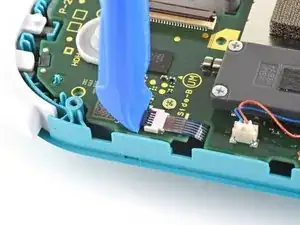
    • Klappe den kleinen, scharnierartigen Sicherungsbügel am ZIF-Verbinder des Kabels zum rechten Joystick mit einem Öffnungswerkzeug oder dem Fingernagel auf.

  31. pEFHSSkWUaqGATlV
    pEFHSSkWUaqGATlV
    eMQ2CE3UiSPwibFF
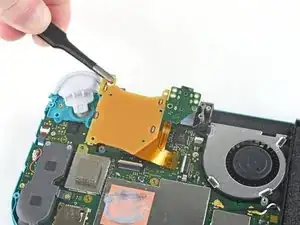
    • Schiebe das Kabel zum rechten Joystick mit einer Pinzette aus seinem Anschluss auf der Hauptplatine heraus.

  32. 3GkQQgnWlLlGONVE
    • Nimm einen JIS 000 Schraubendreher/Bit oder ein Original PH000 Bit von iFixit und entferne folgende sechs JIS-Schrauben, mit denen die Hauptplatine befestigt ist:

    • Drei 3,1 mm Schrauben

    • Drei 4,5 mm Schrauben

    how to get the c port off

    Dustin Cronk -

    When re-assembling, be sure the fan cable (step 25) is completely pulled through prior to tightening the screw that’s right next to it.

    John Glaeser -

  33. dKc6KXcUwADISyuy
    dKc6KXcUwADISyuy
    BWklTKR1T4CAQHCW
    cEYHxoErVSYY1wd3
    • Setze einen Spudger in den Spalt zwischen den Rahmen und der Hauptplatine ein. Hebe dann die Hauptplatine aus ihrer Vertiefung heraus.

    • Entferne die Hauptplatinen-Baugruppe.

  34. e2BhbC1SeeZlIwoR
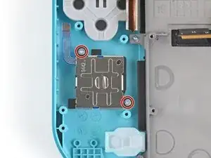
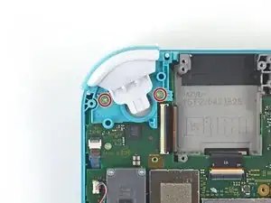
    • Nimm einen JIS 000 Schraubendreher/Bit oder ein Original PH000 Bit von iFixit und entferne die beiden 3,5 mm JIS-Schrauben, mit denen der rechte Joystick befestigt ist.

  35. 55A3frWJ1YylkjOM
    55A3frWJ1YylkjOM
    5HkWFWjBe3NNes2P
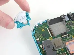
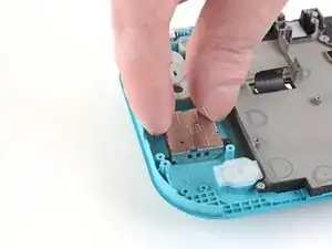
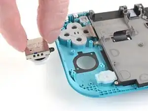
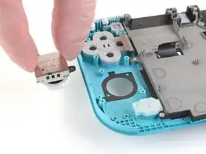
    • Entferne den Joystick mit den Fingern.

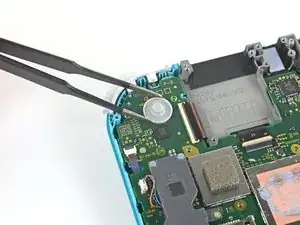
    • Die Öffnung für den Joystick im Rahmen ist mit einer dünnen schwarzen Dichtung abgedichtet. Achte darauf, dass diese Dichtung beim Ausbau des Joysticks nicht verrutscht oder beschädigt wird.

    Where are parts for the right joystick?

    John -

Abschluss

Um dein Gerät wieder zusammenzubauen, folge den Schritten dieser Anleitung in umgekehrter Reihenfolge.

Entsorge deinen Elektromüll fachgerecht.

Lief die Reparatur nicht wie geplant? Probiere zunächst einige grundsätzliche Lösungen oder frage in unserem Nintendo Switch Lite Forum nach Hilfe bei der Fehlersuche.

Craig Lloyd

Mitglied seit: 10/02/16

30062 Reputation

17 Kommentare

Not for the faint of heart and will take much longer than the indicated time. In the end bring it to a professional, as the battery does NOT come off as indicated. I now have an even more expensive repair as the battery socket came off the motherboard.

Craig Osman -

This looked a bit daunting at first, but as you start going you get into a flow and as long as you follow the instructions slowly and carefully you shouldnt have a problem. I would say i finished in the recommended time.

Dom Swooz -

Great guide - completed with no issues easily within the recommended time.
Abelard Snazz -

I did not need to take out the heat sink. It’s a bit difficult. I used this guide and another to replace both buttons.

henreeg -

What did u do so u didn’t need to remove the heat sink? I really dknt want to remove it so I don’t disturb my thermal paste and I don’t want to replace it since I it’s kind of expensive and I dknt want to spend much money doing this repair

ermhs Gpro -

Minor orange juice spill on the rights side, cleaned it quick but the home button and joy stick were a little sticky.

Thank god this guide was so clear, made it easy to check the board for stains and clean up the buttons.

Daniel Peregrym -

I had to replace my right Joy Stick and it went extremely smooth with these instructions.

Jimmy Bailey -

Easy to repair with the correct tools. I found the time estimation to be about right. All around an easy repair, just take your time and be careful to keep the screws organized.

Michael Fox -

Broke my Switch Lite during Step 30 using my fingernail as suggested to flip the switch. It just sheared right off. Now I have a very expensive brick and a fix I paid for that broke it. I am a woman with average-sized hands and grip strength.

Ashley Alderdice -

Super easy and helpful. Got it done in no time. I can't believe how simple this was to do.

Samantha Neller -

Excellent guide. I had 2 to repair; completed the first in 45 minutes, and the second in 30!

Sam Smart -

We replaced both joysticks on my son's Switch Lite, but it will not turn back on now. I went back step by step to confirm everything was connected correctly & put it on the charger, but it will not power on at all. Any suggestions on what I can do?
Wendy Bradley -

any update on it because it happend to me

Isaac Mendez 18 -

I did all of the intrusions and now the switch wont turn on ?

Isaac Mendez 18 -

Probably a loose connection with one of the ribbon cables. unplug and replug, all ribbon cables you have unplug by doing this tutorial and check if you have well reconnect all

Nothing -

How am I the first to notice this?? But there is a critical part missing out of the guide! Its between step 25 and 26. if you look at 25 you can see the cartridge slot intact, (the burnt orange looking thing in the pic), and on step 26 it has magically disappeared with no instruction on how to remove it. Hopefully Ill be able to get it back together because there a cable on the underside of the pcb next to it that needs removed. anyway, proceed with caution

Adam Vogel -

bc im an idiot and missed step 18 somehow, sorry ppl, feel free to remove this post mods

Adam Vogel -