Einleitung

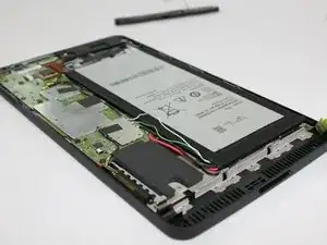
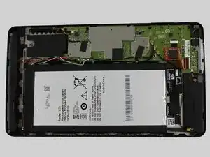
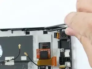
If you noticed your volume buttons are not controlling your volume, and you have tried other methods of raising and lowering your volume, this guide will show you how to replace the volume buttons.

  1. 61fMRxSK2R4sTQo3
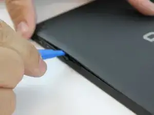
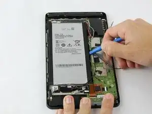
    • Starting at the Micro SD Card Slot and using the blue plastic opening tool, begin to maneuver the tool around the edges while applying light pressure to lift the panel upwards.

  2. nfuWrRUCLRrxCel5
    nfuWrRUCLRrxCel5
    CxCBNQHdHWjc2LFN
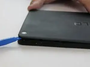
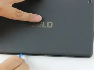
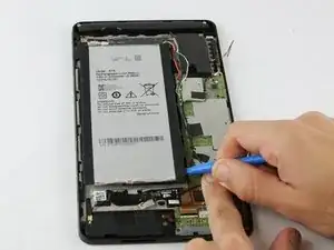
    • There are clips holding the back panel to the rest of the case. You must apply some force to lift the back panel off.

    • Continue lifting up the panel all the way around the edges of the tablet.

    • Once all of the panel clips are unfastened, gently remove the back panel.

  3. ASMI6fYQXUM1DIOT
    ASMI6fYQXUM1DIOT
    MrVbXToAEuRr32JH
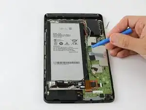
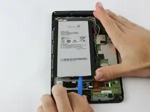
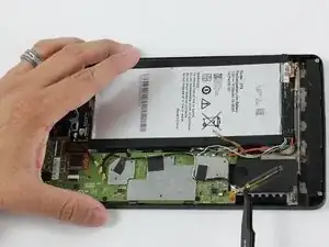
    • The battery is heavily glued down so you will need to apply force while also exercising caution to not damage the rest of the device.

    • Using the blue plastic opening tool, place the lip of the tool underneath the battery as seen in the photo.

    You do not need to remove the battery.

    Dave Bogan -

  4. HQZEPVQJUGPIylZL
    HQZEPVQJUGPIylZL
    Tm1rQqDVjFB1T4HT
    cvMhbB2qtYGkAX6a
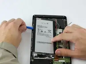
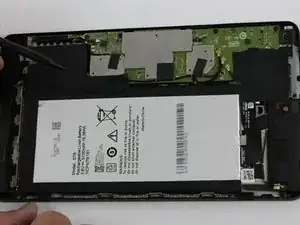
    • Once you have the blue plastic opening tool underneath the battery, work the tool around the edges of the battery similar to the technique used for the back panel.

  5. V5SGHAbEGhNUgQQV
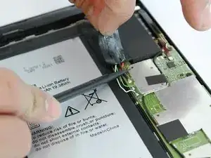
    • When the battery seems loose enough, use the blue plastic opening tool to lift the battery from the device.

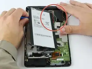
    • The battery has four wires connecting it to the device. Be careful not to damage these wires while removing the battery.

    The white wire is for temperature line. What about the green wire? I have generic battery almost same size ang xapacity but it had only 3 wires, red black ang white. Green is missing

    Alberto MonicaMac103004 -

  6. ZgSEjCbhFcAVy12j
    ZgSEjCbhFcAVy12j
    2hlaHP3VZVOhtvaA
    mJI1nRUxdPVJEptq
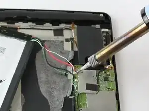
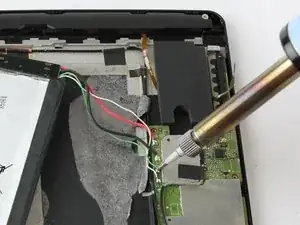
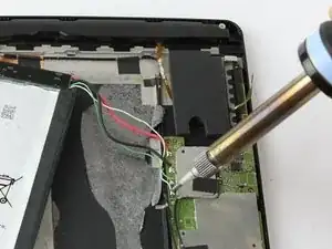
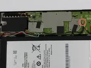
    • The wires to the battery are soldered to the motherboard. You may also check the soldering techniques guide for additional tips on soldering.

    • If your device's wiring doesn't exactly match these photos, snap a picture or make a note of what color wire goes to which contact on the motherboard before you detach them. (A mis-wired battery could cause electrical shorts and ruin the tablet for good.)

    • Using a soldering iron, desolder the four wires from the motherboard.

    • Once the wires are free from the motherboard, your battery should be free to remove from your device.

    Where can I buy a replacement battery??

    Robert Floyd -

    Where can I buy a replacement battery for my Nvidia tablet??

    Robert Floyd -

    Aliexpress -[L508 3,8 V 3,7 V 5000 mAh [3565152] PLIB; polímero de iones de litio/Li-ion batería para tablet pc de autonomía, carga de dispositivos, corrección keystone automática, e-book; BL-T17 celular

    Jose Antonio Fernandez -

    Those replacement batteries only have 2 or 3 wires. Any ideas since the one on the Shield has 4 wires?

    Raul San Martin -

  7. 5GB3FM6FwqFojhp5
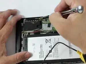
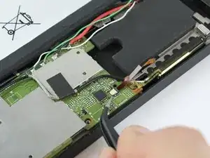
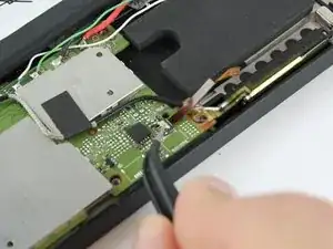
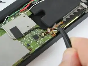
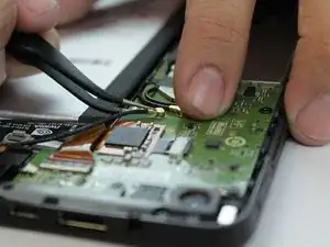
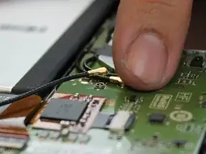
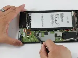
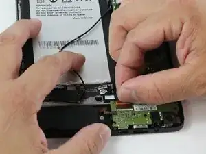
    • Use the angled tweezers to disconnect the black power cable from the mother board. The Cable should pop up from its slot when pulled.

    • Make sure you disconnect the right cables. There are three of these.

    You do not need to disconnect the antenna power cable. You only need to disconnect the other 2 black power cables. Just pull the antenna out together with the Mboard.

    Dave Bogan -

    Did you not remove the battery and disoldered its cables? Why are they still in place?

    Nikos Tsarmpopoulos -

  8. OIuAyGOo1UjgkAmx
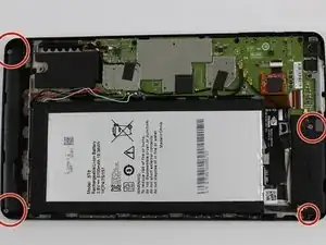
    • Remove the screw adjacent to the WIFI Antenna using the J000 Philips head screw-driver.

    • Screw description: short black screw 20 mm length and 30 mm diameter.

  9. 3F3Sp2MGcPg3YdMi
    • Using the angled tweezers, begin removing the antenna from the device.

    You only need to free the antenna from the case. Leave it hanging from the Mboard.

    Dave Bogan -

  10. VCZQZVZpRAGgDorK
    VCZQZVZpRAGgDorK
    2oXxsNOd6eYhBKSs
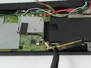
    • The black plastic piece of the antenna is attached to a copper colored film which can be pulled up using the tweezers.

    • The antenna should now be free from the device.

    what replacement part can i use?

    just -

  11. gUWsGW1bbQfDUQNK
    gUWsGW1bbQfDUQNK
    JlyLvDNJQp4Z3h5m
    uKBOCSbeJt4vUiPZ
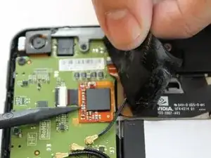
    • Be careful when removing the two pieces of tape because there are wires underneath the tape. Lifting too hard may accidentally rip out the wires.

    • While using the black plastic spudger tool, slowly lift the tape with your fingers and hold the wires down with the tool.

  12. WGLoHqENBNgpbVkS
    WGLoHqENBNgpbVkS
    QNlAWNbboth1BPoJ
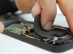
    • The audio input film is running underneath the foam piece and is fragile Be careful when removing this piece.

    • Slowly lift the black foam piece near the WIFI antenna to reveal the audio input film.

    • It is not necessary to remove the foam piece from the device entirely, just as long as you're able to free the audio input film without resistance.

  13. 6PRNFU2YeABGfypp
    6PRNFU2YeABGfypp
    eZWKKaKWGM1WMylP
    iauEYWJbDmjrL3xQ
    • Carefully remove the audio input films for each speaker from their respective ZIF (zero insertion force) connectors. These are the paper thin ribbons that have orange stripes along them.

    • Pull up the white latch on the ZIF connector, which will release the film and allow you to pull it out with tweezers.

    • Repeat this for both speakers.

    How did you remove the antenna in step 10 without removing the audio input films? In this photo, the antenna is still in place. Your instructions are a complete mess!!!

    Nikos Tsarmpopoulos -

  14. CPqWwpqqkQR4gfZl
    CPqWwpqqkQR4gfZl
    TbIOnSM2RY6vALHn
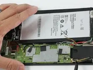
    • Remove the power cables connecting the speakers to the battery. These are black wires with gold tips.

    • Again, use the tweezers to carefully pull them up from their places, they should pop right off.

    • There are three of these black wires in total, but only two belong to the speakers. follow the paths of the wires to make sure they are connected to a speaker.

    Have you not already removed these in Step 7 ???

    Nikos Tsarmpopoulos -

    Removing cables already removed in step 7 ???

    Nikos Tsarmpopoulos -

  15. PEuNBTinUYLBOanK
    • Free the speakers by removing their screws. You'll need the J000 Phillips-head screw Driver.

    • Each screw is roughly 30 mm in length and 30 mm in diameter.

    You only need to remove the speaker on the right of this photo, you can leave the other, longer one, in place.

    Dave Bogan -

    Battery in place, cables soldered, antenna in place, etc, as if you haven’t done any of the previous 14 steps. What a mess…

    Nikos Tsarmpopoulos -

    I think what you meant was 3mm, not 30mm.

    Ken Kawakami -

  16. YIuHSCRytURLfkQY
    YIuHSCRytURLfkQY
    AGLRVXkmOgJDcH3Z
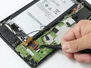
    • Using the tweezers or your fingers lift the remaining black wires from the motherboard.

  17. TeR1y3EGerf2thrb
    TeR1y3EGerf2thrb
    LyiKpf3FIBtDTEX4
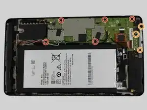
    • Remove the remaining screws holding the motherboard in place.

    • Screws description: 5 short black screw 20mm length and 30mm diameter.

    • Screws description: 3 long black screw 40 mm length and 20 mm diameter.

    Mine had an additional screw on the top left corner of the motherboard. You can actually see it in this picture, directly above the left most screw.

    Eric Jones -

    I just realized that this is the screw described in step 8, which was supposed to be removed by this step. Guess I can't follow instructions.

    Eric Jones -

  18. nkUe5IaSRKEPGDe3
    nkUe5IaSRKEPGDe3
    5sbKuMQnR2vnaN2U
    • Using your fingers, grasp the brown ZIF (Zero Insertion Force) tab and pull outward to disconnect.

    • There is an orange chip that is connected to a white ZIF (Zero Insertion Force). Remove this by using either your fingers or the tweezers.

  19. CofeuVdhcioCIOSR
    CofeuVdhcioCIOSR
    MmtdpiQJXC5LBE2u
    5WNmP1qHECNJGFqO
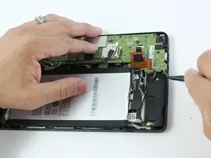
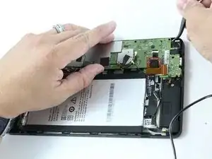
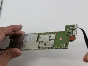
    • Using your tweezers, lightly lift around the edges to lift the motherboard.

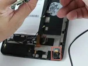
    • When lifting the motherboard around the edge near the rear facing camera, there is a copper cable that is connected underneath the motherboard.

    • Before lifting the motherboard out, use your tweezers to disconnect rear camera's copper cable from the motherboard.

    Congratulations, you’ve just ripped the connector for the front camera when you lifted the motherboard out. The other speaker needs to be removed BEFORE lifting the motherboard, and the front camera, which is glued in, loosened so it lifts out with the motherboard.

    Frank Hovis -

    You can also lift the rear facing camera out. It’s held in only by some double sided tape. This will be necessary to plug it back in anyways.

    Dave Bogan -

    I wish I had read the users’ comments before attempting this repair….

    Nikos Tsarmpopoulos -

  20. Ow2HnRVBikAjwLAX
    Ow2HnRVBikAjwLAX
    SpV2OiLGyBhLMqEL
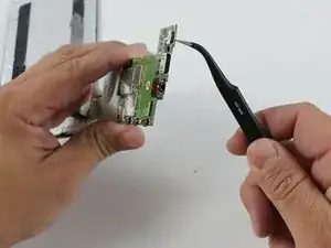
    • Use a soldering iron to desolder the Micro USB Port from the motherboard.

    • Now the Micro USB Port is free from the motherboard.

    You will need to plug in both cameras first and install them together with the Mboard as the connectors are on the underside.

    Dave Bogan -

    BIG NOTE: The entire bottom surface of the usb port is soldered down. You must first desolder the 5 contacts then heat the entire port until it comes loose.

    Dave Bogan -

    How are we supposed to desolder the entire port with a soldering iron alone, as listed in the Tools Section ???? Also, even if I remove the USB port, do I not need a replacement one? Where is it in the list of required parts? The worst iFixIt guide ever !!!

    Nikos Tsarmpopoulos -

  21. puyrrNxiShkgZANY
    • Here are the button switches that are pushed for your Volume Control.

    • This is your power button switch.

    the power button is the bottom button on this picture, not the top.

    Mike Chamberlain -

  22. G63Z4kNwCqU1gkOv
    G63Z4kNwCqU1gkOv
    PtFeqE3FtS5odLNp
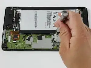
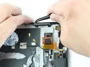
    • Using your black and silver tipped tweezers, remove the volume control.

Abschluss

To reassemble your device, follow these instructions in reverse order.
Ryan Butler

Mitglied seit: 10/02/16

1614 Reputation

0 Kommentare