Einleitung

  1. LmMUhPNXbwsx3fhQ
    LmMUhPNXbwsx3fhQ
    oyZWPUliCHxJMgfT
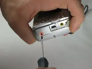
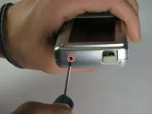
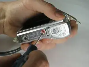
    • Remove the 2 exposed screws on opposite sides of the camera. Turn the screws counter-clockwise to remove.

  2. HSfmLADdO4RXTkGY
    HSfmLADdO4RXTkGY
    NPwW1nkFKnFg462F
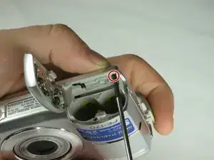
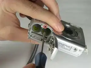
    • Open the battery compartment and remove the 2 screws in the top of the opening.

  3. 2oSjaVDjFPHf42UT
    2oSjaVDjFPHf42UT
    QdSPWdCSEDtTtx66
    • Remove the 2 exposed screws on the bottom of the camera.

  4. TULq4rOj1cMRriRx
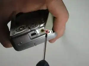
    • Uncover the mini-usb dock on the side of the camera and unscrew the screw next to the flap joint

  5. ABoU1Yu3SnDvxGFQ
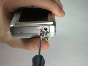
    • Uncover the video cable port on the side of the camera and remove the screw

  6. eF23I4kgN5mLaDJN
    eF23I4kgN5mLaDJN
    vuw6DfRaHZEvZqiB
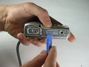
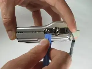
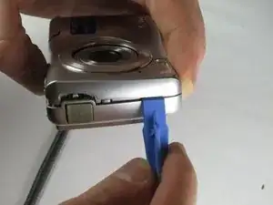
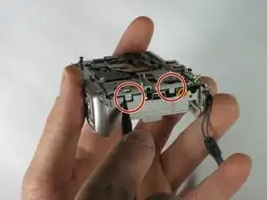
    • Carefully slip the head of the plastic opening tool under the panels by finding the crack between the panels. Lightly apply pressure in the shown places at the top and bottom of the camera.

  7. D2L4ZghG4Gy15pbP
    D2L4ZghG4Gy15pbP
    16u4ymQMWB5NhATH
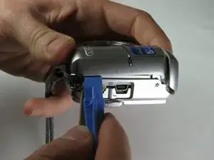
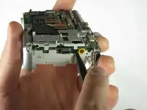
    • Loosen the panels on the sides of the camera in the shown places by slipping the plastic opening tool in the crack between the panels. Lightly apply pressure.

  8. Uh3EXRI2OQnkS3Ug
    Uh3EXRI2OQnkS3Ug
    rYigEFYvkscqnB1P
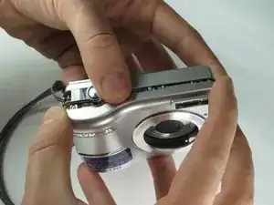
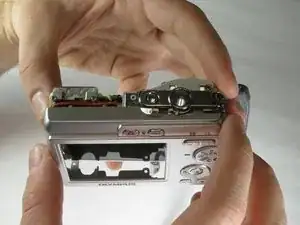
    • Ensure that the panels have been loosened. Carefully use hands to pull back and remove the panels.

  9. k3B6upWJ2yB2GiVe
    k3B6upWJ2yB2GiVe
    mHh4QAjBDubX6Vsb
    NkvXsE5SPW4hXqmZ
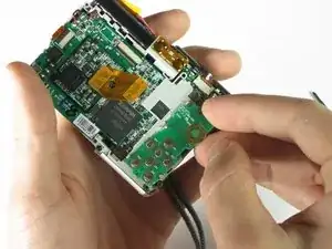
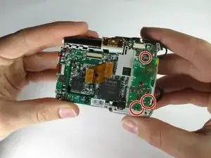
    • Remove the three screws holding the outer circuit board in place.

  10. PaHEACkBBnBDVyV2
    PaHEACkBBnBDVyV2
    ukDOIZZsh6LosMle
    • Use the spudger or your fingers to remove the outer circuit board from the camera.

  11. OweMElccZLlD1GuM
    OweMElccZLlD1GuM
    i2kfCbxMtxtDPgJ1
    mTnUGKnvAedGwfBG
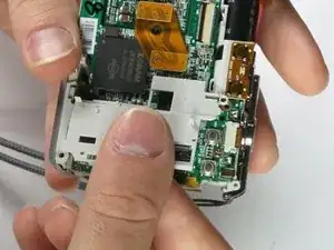
    • Use the spudger to pull the plastic tabs shown off of the motherboard.

    • Gently pull the plastic piece off of the motherboard.

  12. XP4AGTfYKJdFMxxf
    XP4AGTfYKJdFMxxf
    wvsueVIMhvZ124jX
    A6YXqXtukOwbRKut
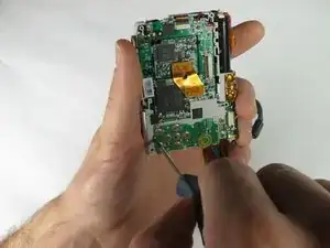
    • Remove the screws shown using the 00 philips screwdriver.

  13. uUntSQsgJBmQUqyX
    uUntSQsgJBmQUqyX
    fDcsJQsaQGKYqcjq
    uG4EkpgHKRkdaYT2
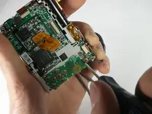
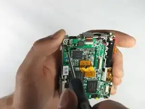
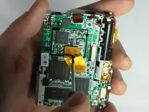
    • Use the pointed end of the spudger to release the ribbon cable clasp.

    • Remove the ribbon cable from the port using the tweezers.

  14. qAri5eMre1BKLDFM
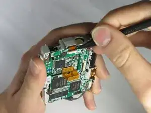
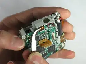
    • Use the tweezers to remove the ribbon cable near the shutter button.

  15. TUl3OW3UTNLdwD2w
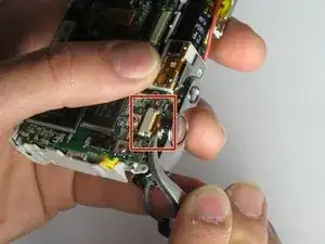
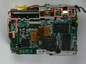
    • Next unsolder the connections shown.

    • See our soldering guide for help on how to unsolder

    • Soldering irons are hot, and will also heat the connection wire. Using the tweezers will protect your fingers from the heat.

  16. rRyM5Rlsh4SK2PQ2
    rRyM5Rlsh4SK2PQ2
    hi6OTAYkoxCD2ZZT
    5FTanXsA1RIfZFvC
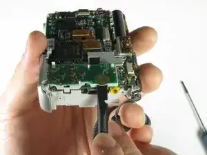
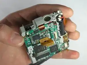
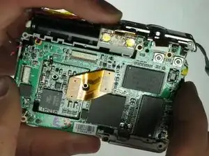
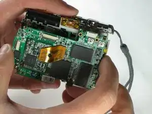
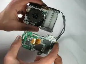
    • Gently pull the motherboard (from the bottom first) away from the device.

Abschluss

To reassemble your device, follow these instructions in reverse order.
Tyler Hartwig

Mitglied seit: 24/03/15

337 Reputation

0 Kommentare