Einleitung

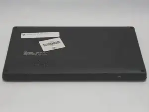
If the device fails to charge or connect to a computer, consider using this guide to replace the USB charging port.

  1. GbCYnWI5VIOu4RYw
    GbCYnWI5VIOu4RYw
    GBNQaw1BfWqhBm2F
    • Turn off and unplug the device before starting replacement.

    • Flip the device so that the screen faces down, with the back facing up.

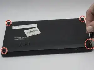
    • The back panel attaches to the device with four 4.0mm long screws, one at each corner, indicated by the red circles in the picture.

    • Unscrew the four screws with a PH000 screwdriver.

  2. Suf2NRN1XNd3nLNk
    Suf2NRN1XNd3nLNk
    JhvOPgxmlDo1NrAG
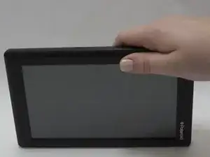
    • Flip the device over so that the screen faces up, and the back faces down.

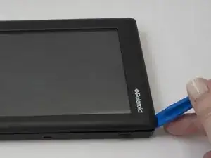
    • Separate the front panel using the Opening Tool on a corner to create an opening.

    • Removing the frame for the first time may take a significant amount of force.

    • Run the tool along the seams of the device to open up all the sides.

  3. 2YURiJe1wlWrejMO
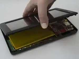
    • Removing the panel too quickly may damage the cable that attaches parts between the two panels.

    • Gently lift the top panel from the bottom panel.

  4. rF6YepwNGeqF2Smw
    rF6YepwNGeqF2Smw
    pOGi5RDZxgeFhMYT
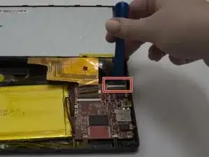
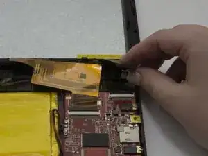
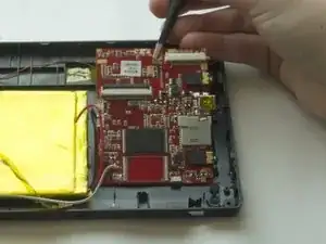
    • The flexible flat cables (FFC) attach to parts in the bottom panel with zero insertion force (ZIF) connectors.

    • Use the Opening tool to flip up the black retaining flap on the smaller connector.

    • Gently lift the cable, parallel to the panel, to detach it.

  5. LwQUaYNVmY1LVHwV
    LwQUaYNVmY1LVHwV
    5VMCyhlDwTilcTZ4
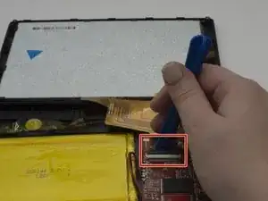
    • Use the Opening tool to flip up the black retaining flap on the larger connector.

    • Gently lift the cable, parallel to the panel, to detach it.

  6. wH33GtBMKZjsnuCC
    wH33GtBMKZjsnuCC
    GgvBrSOufmRfLjwV
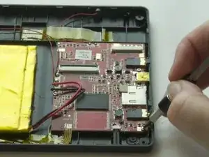
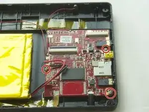
    • The motherboard attaches to the back panel with three 3.5mm long screws.

    • Unscrew the three screws with a PH000 screwdriver.

  7. vIrPCmmYLrgRNCoX
    vIrPCmmYLrgRNCoX
    lnFSePVsh3uQYWZs
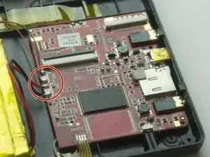
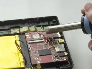
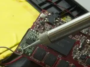
    • Solder beads attach the wires that connect the motherboard to other parts, such as the battery and the speaker.

    • Desolder the wires from the motherboard. For detailed information, refer to the Solder and Desolder guide.

  8. T5FNVeGq3api5UaP
    T5FNVeGq3api5UaP
    c3yBlwcB3Ur1tgRg
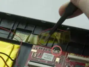
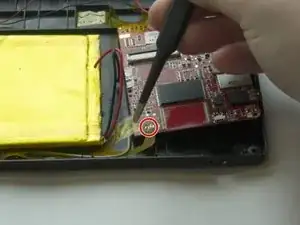
    • Some of the wires attach to the panel with tape as well.

    • Use tweezers to gently lift the tape from the wires and plastic.

    • Desolder the wires from the motherboard.

  9. xxuoHnlqwAiJ4pyi
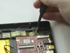
    • Use tweezers to gently lift the yellow tape that tapes down the yellow flat cable.

    • Desolder the flat cable.

  10. lsIYhSMqOoy4gRqW
    lsIYhSMqOoy4gRqW
    DcRvtW2QElUsBO1X
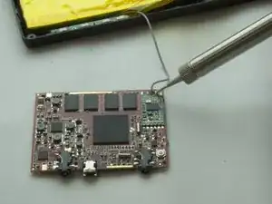
    • There is a grey wire attached to the back side of the motherboard.

    • Flip the motherboard over to the side so that the grey wire and its solder bead faces up.

    • Desolder the gray wire from the motherboard.

  11. DZqeutAyFX2KAn6g
    DZqeutAyFX2KAn6g
    hKKfoylQab6iONJ5
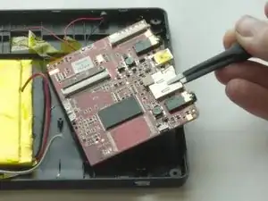
    • Use tweezers to lift the motherboard from the panel.

Abschluss

To reassemble your device, follow these instructions in reverse order.
Amy Li

Mitglied seit: 01/02/17

627 Reputation

0 Kommentare