Einleitung
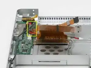
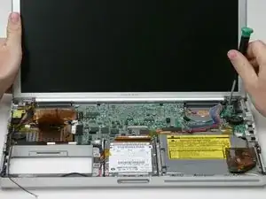
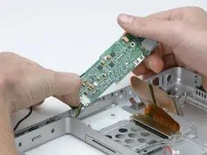
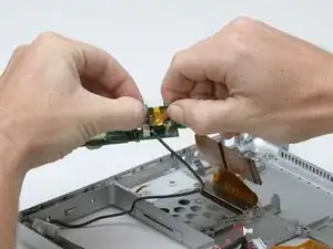
This unit provides power to the machine, allows the battery to charge, and provides sound capability.
Werkzeuge
Ersatzteile
-
-
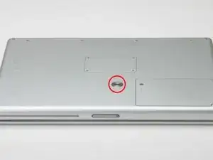
Use a coin to turn the battery locking screw 90 degrees clockwise.
-
Lift the battery out of the computer.
-
-
-
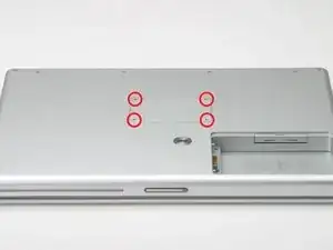
Remove the four Phillips screws from the memory door.
-
Slide the memory door away from the memory compartment.
-
-
-
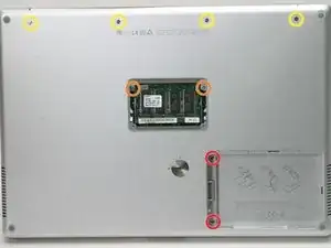
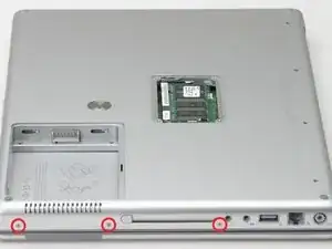
Remove the following 8 screws:
-
Two 3 mm Phillips in the battery compartment, on either side of the battery contacts.
-
Two 9 mm Phillips on either side of the memory compartment.
-
Four 16 mm Phillips along the hinge.
-
-
-
Rotate the computer 90 degrees clockwise, so that the power receptacle faces you.
-
Remove the three 3 mm Phillips screws.
-
-
-
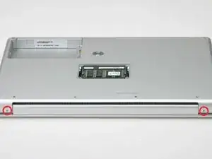
Turn the computer 90 degrees clockwise so that the hinge faces you.
-
Remove the bottom 5 mm Phillips screw on either side of the hinge (two total).
-
-
-
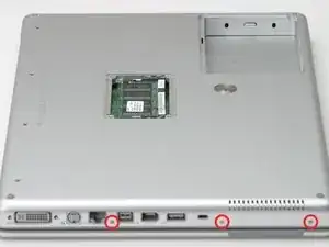
Rotate the computer 90 degrees clockwise, so that the ports face you.
-
Remove the three 3 mm Phillips screws.
-
-
-
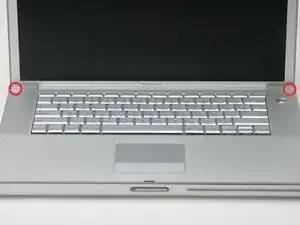
Turn the computer over and open the display.
-
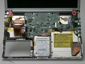
Remove the 4.2 mm 1/16" H 1.5 hex screws in either corner, next to the display (a T6 Torx driver will also do the job nicely).
-
-
-
Grasp the back corners of the upper case and pull up, disengaging hidden tabs on the sides. Do not pull the upper case off yet; you still need to free tabs in the front of the case.
-
-
-
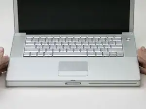
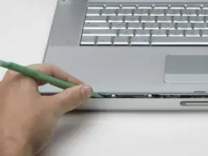
Pry up the left side of the upper case slightly with your hand and wedge a spudger into the seam between the upper case and lower case.
-
Leave the tool in place applying pressure to the upper case for the next step.
-
-
-
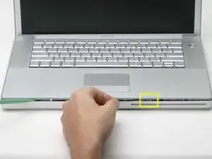
Place enough pressure on the upper case to allow you to slide a tool just within the seam between upper case and lower case as shown in the picture. A dentist's hook, push pin, or similar tool will work.
-
Delicately slip the tip of your tool behind the silver metal latch and pull it forward while pulling up on the case. This may take some effort.
-
Alternatively, you can free the clasp with a small flathead screwdriver through the CD slot. The clasp is 1-3/16 in (3cm) from the left side of the slot. Use the screwdriver to lift out (or press back) the felt lining; then use the screwdriver to pull the clasp (shiny metal) forward to free it from the catch behind it (dull metal).
-
-
-
Lift the back of the case up and work your fingers along the sides, freeing the case as you go. Once you have freed the sides, you may need to rock the case up and down to free the front of the upper case.
-
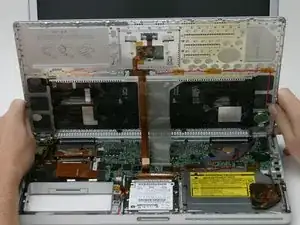
Rotate the upper case up and toward the screen, so that the upper case rests against it.
-
-
-
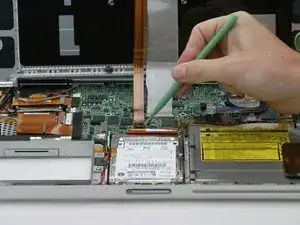
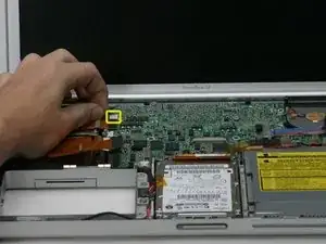
Remove the orange tape securing the trackpad ribbon to the logic board.
-
Disconnect the trackpad ribbon from the logic board.
-
-
-
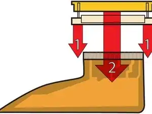
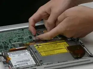
1) With your fingernails, grasp the locking bar on either side and pull up a small amount (about 1/16" or 2 mm).
-
2) After disengaging the locking bar, slide the cable out of the connector.
-
-
-
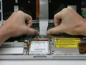
Loosen the keyboard ribbon clamp by pushing the thin black piece toward the screen, using the tips of your fingers.
-
Slide the grey keyboard ribbon out of the loosened connector.
-
Remove the upper case from the computer.
-
-
-
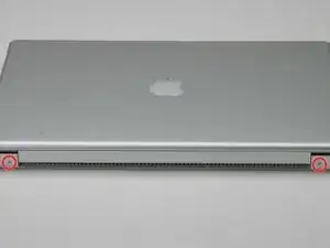
Close the display and turn the hinge side of the computer to face you.
-
Remove the remaining Phillips screw on either side of the hinge (two screws total).
-
-
-
Open the computer with the display facing you.
-
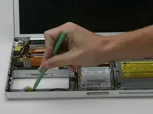
Use a spudger to pry the bluetooth board from the gap between the battery housing and front of the lower case.
-
-
-
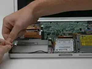
Disconnect the bluetooth antenna cable from the bluetooth board.
-
Deroute the bluetooth antenna cable along the left edge of the computer, removing tape as necessary.
-
-
-
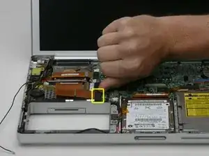
Pull the Airport ribbon cable up in order to access the black Airport antenna connector.
-
Disconnect the Airport antenna cable at the black connector, making sure you pull only on the black rubber portion of the connector.
-
-
-
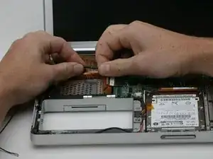
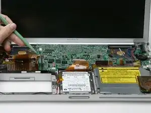
Remove the two pieces of orange tape covering the display data cable and disconnect the cable from the logic board.
-
-
-
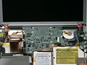
Remove the T8 Torx screw closer to the display on either side of the hinge (two screws total).
-
-
-
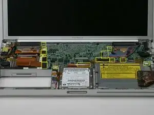
Disconnect the indicated 14 cables from the logic board, starting in one place and moving around the board.
-
-
-
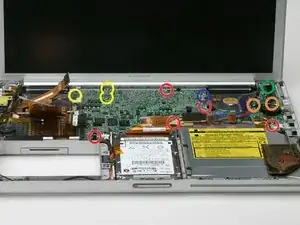
Remove the following 12 Phillips screws from the logic board:
-
Six 4 mm around the edges of the logic board.
-
Two 5 mm securing the right speaker to the logic board (move the speaker off of the logic board).
-
Three 6 mm with wavy washers in the upper, left corner of the logic board.
-
One 4 mm underneath a black bumper in the back right corner of the logic board.
-
One 4 mm screw may not be present on some logic boards.
-
-
-
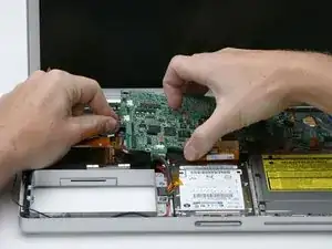
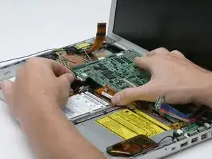
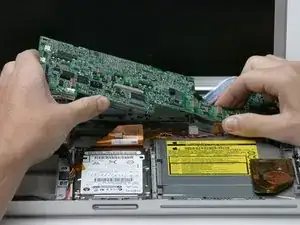
Grasp the logic board at the left edge with one hand and at the thinnest section with the other hand. Lift the left edge of the board up to approximately a 30 degree angle (if you don't have your protractor handy, just lift until the DVI port clears the right hinge).
-
Once the logic board clears the ports, slide it out to the left.
-
-
-
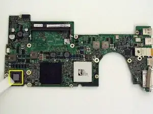
Use a firm plastic edge to scrape the thermal material off the processor.
-
For more advanced instructions on this procedure, see our Applying Thermal Paste Guide.
-
-
-
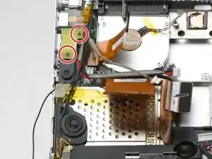
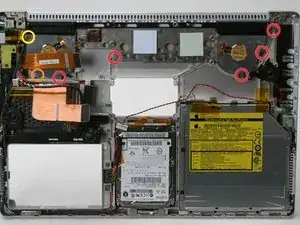
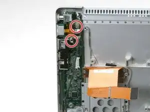
Remove the two black Phillips screws from the yellow plastic board above the USB port on the left side of the computer.
-
-
-
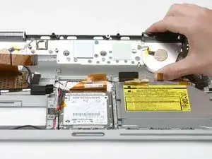
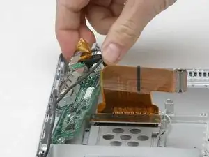
Lift the speaker board up from the computer so that you can access and disconnect the speaker cable from the sound board.
-
Remove the speaker assembly entirely, including the right speaker.
-
-
-
Remove the following 7 Phillips screws attaching the heat sink to the metal framework:
-
Five 5 mm screws scattered around the heat sink.
-
One 6 mm on the front left corner of the heat sink.
-
One 10 mm in the back left corner of the left fan.
-
-
-
Remove the heat sink from the case, minding the left corner, as it tends to catch in the case (the fans will come out with the heat sink).
-
-
-
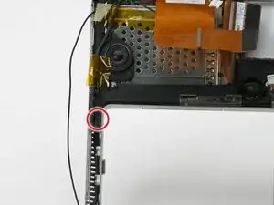
Remove the T8 Torx screw from the RJ-11 board.
-
Remove the 5 mm standoff that secures the DC/Sound card to the lower case using a nut driver or pliers.
-
-
-
Use your thumbs to slide the RJ-11 board away from the sound card in the same direction you would disconnect a cable. This is your chance to get out some aggression, as the board will most likely be very tight and requires a good deal of force to remove. Don't get carried away though - don't hold onto the power connector and don't put too much actual force on the card itself.
-
1
3 Kommentare
Note regarding re-assembly:
I disassembled the PowerBook to replace a faulty DC board and then began performing the steps in reverse to reassemble.
When I arrived at step 38 I realized that I needed to loosen the torx and hex I tightened in step 43 in order to properly align the holes in the DC / sound board to install the PC Card carriage. Once I had the holes lined up and the phillips reinstalled in the PC Card carriage I re-tightened the torx and hex and carried on counting down.
Tim -
Many thanks for this excellent guide!
My Powerbook is now charging batteries again and hopefully won't shut off when it decides it's worked too hard for the day! :-)
My only note: I was impatient with the keyboard ribbon cable and didn't understand your diagrams until it was too late. I used a fingernail to try and release the left side clip (white plastic)... which I broke off, it's not a clip mechanism, just a spring retainer. you just need to release the black plastic bar in the back under the ribbon cable, there is NO CONNECTOR on the cable, it;s just sort of a pressure fit!
I got it back together and had to use a piece of tape to hold it together... hope that works, unless anyone has a better idea. This laptop won't do much traveling any more, so I hope it will hold.
I also scraped and reapply thermal paste to the GPU chip and the big apple chip in-between (3 total).
CPU temp is running at 59 deg Celcius... hoping that is good? More research is needed.
Many thanks again!
Cfreak -
Well, my PB G4 charged batteries for ca. 1 hour just after the repair 2 weeks ago and then decided it had had enough and hasn't charged a battery since. I did notice it got very hot while charging batteries for that hour. I had scraped and reapplied thermal paste to all 3 of the of the chips on the mobo (CPU, GPU and the one in the middle), so I don't think it was due to that.
I have just replaced the PRAM battery, after determining with apple's guide that it was not able to hold a charge and reading that it can affect charging. Still not charging batteries! Tried two different 65 watt power supplies too. Uggggh. Any ideas?
Cfreak -
