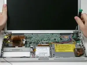
Einleitung

56k internal modem, standard on all models.

  1. cSjY4VwZCbhFeh5r
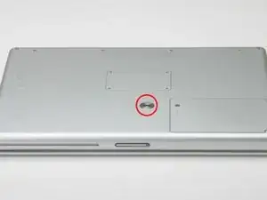
    • Use a coin to turn the battery locking screw 90 degrees clockwise.

    • Lift the battery out of the computer.

  2. cvgou5gisUpXdPoI
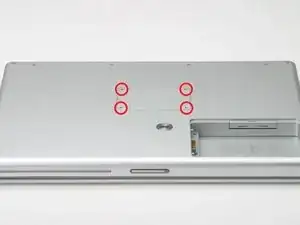
    • Remove the four Phillips screws from the memory door.

    • Slide the memory door away from the memory compartment.

    Do you actually need to remove any of the screws on the underneath if you're just replacing a PRAM battery, or a hard drive? Aren't those only required if you're taking the whole logic board out?

    Tom Anderson -

  3. WjURICf5GMXBfdXY
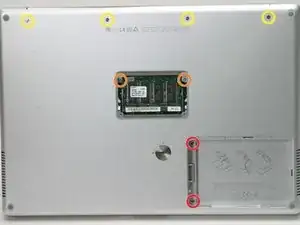
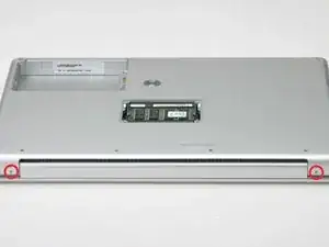
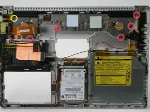
    • Remove the following 8 screws:

    • Two 3 mm Phillips in the battery compartment, on either side of the battery contacts.

    • Two 9 mm Phillips on either side of the memory compartment.

    • Four 16 mm Phillips along the hinge.

  4. NhXgjAkxB2DuiQAY
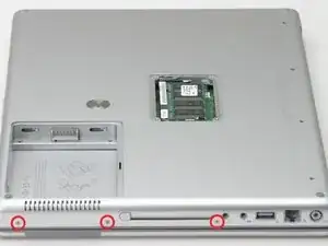
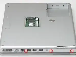
    • Rotate the computer 90 degrees clockwise, so that the power receptacle faces you.

    • Remove the three 3 mm Phillips screws.

    • When replacing these screws, you must place each screw in the correct order. Begin by installing the screw closest to the display hinge, and go out from there.

  5. mU1qZe6FJbnseXae
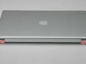
    • Turn the computer 90 degrees clockwise so that the hinge faces you.

    • Remove the bottom 5 mm Phillips screw on either side of the hinge (two total).

    The two "bottom" 5mm philips screws here are the ones closest to the display. (as shown in the image)

    seos -

    "Bottom" assumes you have the computer upside down. If you can see the Apple on the front, then remove the two "top" screws...

    Kevin -

  6. KPqtUFIKBUvLYX1k
    • Rotate the computer 90 degrees clockwise, so that the ports face you.

    • Remove the three 3 mm Phillips screws.

    • When replacing these screws, you must place each screw in the correct order. Begin by installing the screw closest to the display hinge, and go out from there.

  7. fSW1Z24IfphoxqAC
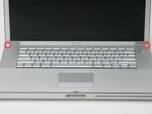
    • Turn the computer over and open the display.

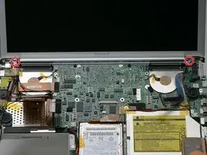
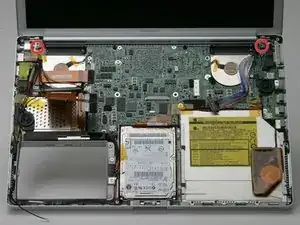
    • Remove the 4.2 mm 1/16" H 1.5 hex screws in either corner, next to the display (a T6 Torx driver will also do the job nicely).

    I found that the T6 was too small but a T7 worked, with a little push downward to make it sit inside the hex head.

    dougcabot -

    My T6 worked very well on these 2 screws.

    David Parker -

  8. pFlpx3cwKfiYmwMN
    • This step covers the hardest part to get inside this computer. Take a deep breath and think happy thoughts.

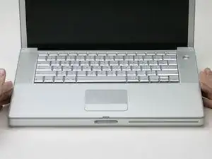
    • Grasp the back corners of the upper case and pull up, disengaging hidden tabs on the sides. Do not pull the upper case off yet; you still need to free tabs in the front of the case.

    • The seam is beneath the plastic molding on the upper case.

    I've opened the G4 four times. The official Apple way outlined above is vastly superior to the paper clip method. When you lower the screen side of the deck, a little bit of pressure toward you will easily release the clips. Definitely begin with the back (screen side) of the deck where you just remove the two T-6 screws.

    wcwirla -

  9. ZhqOaIOAMBkKfDDM
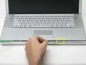
    • There is one latch that stops you from pulling the upper case right off, located on the left side of the optical drive slit. To free the upper case, you will be pulling a thin metal latch toward you, freeing it from the clasp holding it in place.

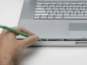
    • Pry up the left side of the upper case slightly with your hand and wedge a spudger into the seam between the upper case and lower case.

    • Leave the tool in place applying pressure to the upper case for the next step.

    This could really use a diagram to show exactly how the clip is structured. I didn't realize the clip was between the front of the case and the back support it attaches to, and it needs to be pried off that back support. (Evil Apple design - would it really hurt to have a screw underneath?). Overall these guides are fantastic! I just replaced a hard drive, and it worked great. And I LOVE the screw guide at the back - brilliant idea!

    isonno -

    Apple official disassembly guide suggests instead to lift the upper case from the back up to 45 degrees. Then while lowering it back gently wiggle the upper case and it does disengage the latches. No tools required, no risk of bending the case.

    John -

    This method worked perfectly for me. Lift at 45 degree angle and wiggle as slowly lower and it popped right off.

    th3mamma -

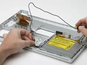
  10. oLUOLwm61kpj3sX1
    • Place enough pressure on the upper case to allow you to slide a tool just within the seam between upper case and lower case as shown in the picture. A dentist's hook, push pin, or similar tool will work.

    • Do not yank the upper case off as soon as you free the clasp. The case is attached to the logic board via two ribbon cables.

    • Delicately slip the tip of your tool behind the silver metal latch and pull it forward while pulling up on the case. This may take some effort.

    • Alternatively, you can free the clasp with a small flathead screwdriver through the CD slot. The clasp is 1-3/16 in (3cm) from the left side of the slot. Use the screwdriver to lift out (or press back) the felt lining; then use the screwdriver to pull the clasp (shiny metal) forward to free it from the catch behind it (dull metal).

    I was able to easily release the latch by putting the spudger in the optical drive slot, and gently prying up. You can see the three holes where the upper case clips in above the drive, and the clips are accessible through those holes from the optical drive slot.

    ryan64 -

    "Forward" (step 10) means toward the front. I was not able to release the latch this way. However, I did eventually release all three latches at once by very slightly lifting the rear of the cover and pressing the cover back toward the screen.

    It is not necessary to remove the trackpad and keyboard cables (steps 12, 13, and 14) to replace the hard drive.

    Pomo -

    Zitat von Pomo:

    "Forward" (step 10) means toward the front. I was not able to release the latch this way. However, I did eveIt is not necessary to remove the trackpad and keyboard cables (steps 12, 13, and 14) to replace the hard drive.

    I find it useful to use a big rubber band to hold the keyboard up--put it around the keyboard and display.

    colleenthompson -

    I've done several of these before, but today it was a bear to accomplish. I finally did it by inserting a dental pick through the optical slot and pulling forward to release the clip. In case it will help someone else, pictures of the clip are at Devil Clip.

    colleenthompson -

    I did not find any clip to disengage to remove the top piece. I would like to have seen a picture of the clip after the the top was separated.

    Oh, well. This guide is probably not much use to anyone any more.

    Chrissy -

  11. bHonKwrREyijwfMP
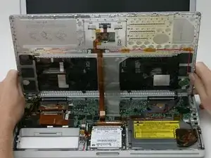
    • Lift the back of the case up and work your fingers along the sides, freeing the case as you go. Once you have freed the sides, you may need to rock the case up and down to free the front of the upper case.

    • Rotate the upper case up and toward the screen, so that the upper case rests against it.

    The top assembly for the A1138 model (1.67MHZ high res) does not have two ribbon cables to connect to the logic board as pictured.

    Mike -

  12. V5nEImLmEdjNtMfY
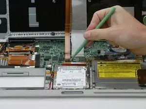
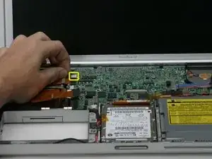
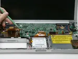
    • Remove the orange tape securing the trackpad ribbon to the logic board.

    • Disconnect the trackpad ribbon from the logic board.

    If you are just replacing a hard drive, you do not need to remove either the trackpad or the keyboard cables! They will not be in the way at all. Save yourself a headache.

    dougcabot -

    I agree - removing the cables is not necessary. I didn't even have a keyboard cable on my machine.

    macbaen -

    i agree, too:

    steps 12 to 14 are NOT necessary for replacing the harddrive!

    neither are 17 and 18!

    instead:

    after 10 continue with step 15.

    instead of 17 and 18: free the hd carefully

    from the case disconnect the hard drive cable from the hard drive.

    valid -

  13. hBg3NSEtSTq4HSHD
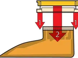
    • This is a diagram of the keyboard ribbon clamp connector you will disconnect in the next step.

    • 1) With your fingernails, grasp the locking bar on either side and pull up a small amount (about 1/16" or 2 mm).

    • 2) After disengaging the locking bar, slide the cable out of the connector.

    Be very careful! The clasps holding the black strip are extremely fragile and can snap very easily.

    ChrisT4 -

    Zitat von ChrisT4:

    Be very careful! The clasps holding the black strip are extremely fragile and can snap very easily.

    In fact it is possible to get to your hard drive and replace it without having to detach this ribbon at all and I would advise that if all you are doing is replacing your hard drive then skip this step.

    ChrisT4 -

    My laptop did not have the big gray keyboard ribbon but a short white one with a blue stripe at the end. Anyone knows if this is just a different setup?

    afido -

    my g, 15", 1.5Ghz pbk didn't have this cable at all. It's short white kbd cable attached to the trackpad, and it's orange ribbon cable (only) attached to the logic board as in step 12. lucky me.

    gogreens -

    Yes, the note about skipping this step should be up there, front and center. I followed this step and broke the bit of plastic. Now it's re-fastened with a piece of electrical tape, but I am annoyed because it was totally unnecessary to do that. How do we edit the front page to at least say "OPTIONAL" for this step?

    Focus Fusion Society -

    There should be a note on this to say this step is OPTIONAL. I followed instructions as written, broke the little plastic piece, and have taped it back together with electrical tape. But after replacing the hard drive, I see it was totally unnecessary to take this step. It's a high risk step, people should be warned.

    Focus Fusion Society -

    the diagram is a bit confusing, and the text is a bit confusing for non english speakers. when it said pull up a small amount, i thought you have to try and lift it from the motherboard. all you have to do is move the black plastic bit towards the screen with your fingernails and the broad thing plastic keyboard cable comes off.

    Kiureli -

  14. cqv2OdxSNuuCNS6F
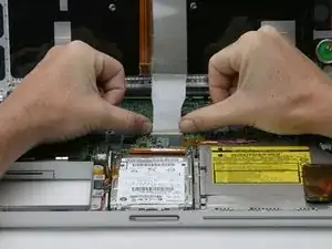
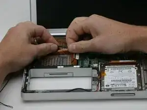
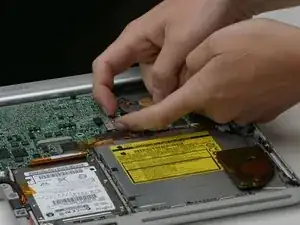
    • Loosen the keyboard ribbon clamp by pushing the thin black piece toward the screen, using the tips of your fingers.

    • The black piece is very fragile and easily broken. Use care when separating it from the main socket.

    • Slide the grey keyboard ribbon out of the loosened connector.

    • Remove the upper case from the computer.

    My machine didn't have a keyboard ribbon.

    macbaen -

    Watch this step carefully! The release mechanism pushes back slightly, parallel with the surface of the logic board. You may want to gently use a sparger rather than your thumbs if you have big fingers. This is a very delicate connector. Work one side slightly then the other. The good news is that it does not offer any resistance.

    wcwirla -

    I've found, however, that it's not necessary to remove the cables and thus risking breaking these fragile parts. The still-attached keyboard can simply be rested against the screen/lid of the machine while the rest of the work is done.

    Charles Ess -

  15. Rmhd1ThVMI4fFAXl
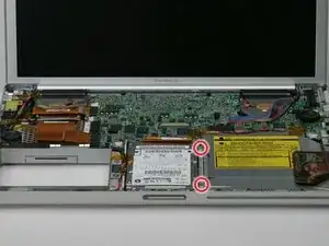
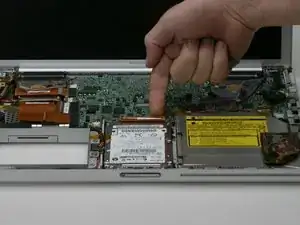
    • Remove the two 6 mm long silver Phillips screws from the metal bracket to the right of the hard drive, removing tape as necessary.

    These are the 6 mm silver (not stainless) screws. Don't use the longer 9 mm silver screws (for battery compartment) by mistake and have to take everything apart again to retrieve them. Like I did of course.

    Pomo -

    Zitat von Pomo:

    Don't use the longer 9 mm silver screws (for battery compartment) by mistake

    I didn't bother removing the ribbon cables, it was easy enough to get the hard drive out of there. In total I had 8 different types of screws (and 7 if I grouped the ones in the ram and battery compartments together, to avoid this problem) and found that a 7 day pill case worked perfectly for arranging them in the correct order for reassembly.

    qufighter -

    I had 3 long screws on my bracket.

    macbaen -

  16. eby1kWPOHE2fukMB
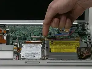
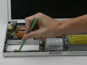
    • Use a spudger to lift the metal bracket out of the computer.

  17. g4KVtMU5VJINqEoB
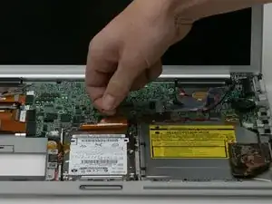
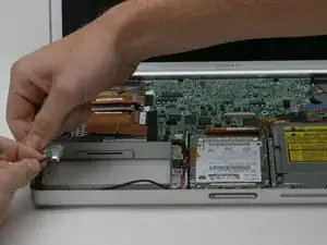
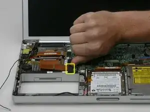
    • Disconnect the large orange hard drive cable from the logic board, removing tape as necessary.

  18. rBVi3JVaGeYF3N4O
    • Deroute the red and black speaker cable from under the fold in the hard drive ribbon.

  19. G6gPJVvM6UwRM2fE
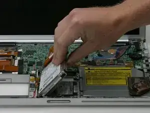
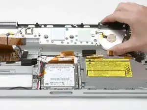
    • Lift the hard drive up from the right side and remove it from the computer.

  20. rakRNrSxwkn6vDXo
    • If you have already removed the hard drive or optical drive, your computer may differ slightly from the images in this section. These parts do not affect this procedure.

    • Close the display and turn the hinge side of the computer to face you.

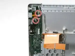
    • Remove the remaining Phillips screw on either side of the hinge (two screws total).

  21. QjQKpXHDtGmhZ5wW
    • Open the computer with the display facing you.

    • Use a spudger to pry the bluetooth board from the gap between the battery housing and front of the lower case.

  22. PRyUdSIWwFk5SSrR
    • Disconnect the bluetooth antenna cable from the bluetooth board.

    • Deroute the bluetooth antenna cable along the left edge of the computer, removing tape as necessary.

  23. DalKKeloRsPeioYn
    • Disconnect the large orange Airport ribbon from the logic board.

  24. ZHRGu1k2wcX3D4Fj
    • Pull the Airport ribbon cable up in order to access the black Airport antenna connector.

    • Disconnect the Airport antenna cable at the black connector, making sure you pull only on the black rubber portion of the connector.

    my airport antenna cable has no connector and it doesn't run under the Airport ribbon cable, but instead runs under the PCMCIA card slot to god knows where. urgh, am wondering if I'm following the right guide for my g4, 15: 1.5Ghz Pwrbk.

    gogreens -

    It WAS the right guide, but my machine was missing an Airport cable connector, so I had to remove a half-dozen screws and a nut, loosening some black plastic that was screwed under the modem card, allowing access to remove the PCMCIA receptor (tricky getting it unhooked from the card ejector button), then removing the Airport card in order to unplug the cable.

    gogreens -

  25. fmCMC51rLAjNqPQF
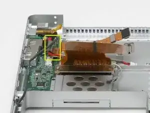
    • Disconnect the inverter cable from the logic board.

  26. 3dGR4VWfB1LTVO2E
    • Remove the two pieces of orange tape covering the display data cable and disconnect the cable from the logic board.

  27. 3OqeIfy6YuSjSKqB
    • Make sure you've freed up all four cables attached to the display assembly, and will pull away easily with the rest of the display.

    • Remove the T8 Torx screw closer to the display on either side of the hinge (two screws total).

    bluetooth cable and airport cable pass under other bundle of cables between 0624 and N47822

    Denis -

    I found T8 torx to be small. I removed and installed those screws with T9.

    Přemek Hnilica -

  28. xpJU5bX3hiVNYHof
    • Be sure to support the display with one hand while removing the final two screws.

    • Remove the longer T8 Torx screw remaining on either hinge (two screws total).

    I found T8 torx to be small. I removed and installed those screws with T9.

    Přemek Hnilica -

  29. X1IN44lREGkRtRWa
    • Lift the display off.

  30. o1kIXKXmGlbThIOm
    • If you have already removed the display or hard drive, you may have already removed some of the cables described in this step. You may also ignore their presence in the following images; they do not further affect the disassembly procedure.

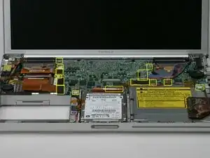
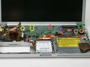
    • Disconnect the indicated 14 cables from the logic board, starting in one place and moving around the board.

    When reassembling you might want to remember to reconnect the battery cable BEFORE tightening the logic board in place.

    Same goes for the cable from the power supply.

    Both can be done afterwards but it's a pain, better done before securing the board in place.

    Carlos Ferrari -

  31. PDys1uxOfN1GtDGo
    • There should be no cables connected to the top of the logic board at this point.

    • Remove the following 12 Phillips screws from the logic board:

    • Six 4 mm around the edges of the logic board.

    • Two 5 mm securing the right speaker to the logic board (move the speaker off of the logic board).

    • Three 6 mm with wavy washers in the upper, left corner of the logic board.

    • One 4 mm underneath a black bumper in the back right corner of the logic board.

    • One 4 mm screw may not be present on some logic boards.

    I only found 5 red screws

    nic9 -

    It really helps to remove the torx that clamps down the display ribbon cable, located on the display hinge. Removing it frees the display ribbon to be moved out of the way a little when you soon pull out the logic board.

    stevesontheroad -

    Zitat von nic9:

    I only found 5 red screws

    Same here, only 5, and also no black bumper covering the 4 mm in the upper right hand corner

    stevesontheroad -

    I have "professionals" repairing my PowerBook before and i notice missing screws!!

    cbeanenyc -

    to get the orange screws out had to take of the small board (one small black screw), plastic support held by green screw.

    Denis -

    There are 2 screws holding the right speaker on place, one of them might be 'hiding' underneath a tiny board that seems to be a sensor (ambient light sensor?).

    Very important to note that you must remove that tiny board too.

    Carlos Ferrari -

  32. 5MsuRILAfHEMnWkF
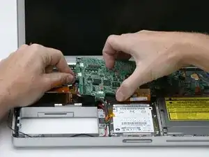
    • Two cables still connect to the logic board and must be removed before pulling the board entirely out of the computer.

    • Use a spudger to gently (very gently) pry up the left side of the logic board.

    step 17 very difficult to pry up. logic board seem to be sticked to the fan module

    cbeanenyc -

    I m stuck here. i had the logic board replaced before by "professionals" at a reputable apple authorized service provider in nyc. somehow the board is stuck to the heat sink near the left fan. i wonder if they used something else than thermal paste, like glue?

    what to do next?

    cbeanenyc -

    Zitat von cbeanenyc:

    I m stuck here. i had the logic board replaced before by "professionals" at a reputable apple authorized service provider in nyc. somehow the board is stuck to the heat sink near the left fan. i wonder if they used something else than thermal paste, like glue?

    what to do next?

    Mine was stuck like that too. I ended up getting a flathead screwdriver and carefully prying up on the edge of the logic board in the back and it came off with an awful sounding pop. It looks like the processor was attached to the heat sink with something that is probably thermal paste. It doesn't seem to be damaged, but I haven't been able to test it yet.

    revcompgeek -

    please let me know if your logic board is working

    cbeanenyc -

    Zitat von revcompgeek:

    Mine was stuck like that too. I ended up getting a flathead screwdriver and carefully prying up on the edge of the logic board in the back and it came off with an awful sounding pop. It looks like the processor was attached to the heat sink with something that is probably thermal paste. It doesn't seem to be damaged, but I haven't been able to test it yet.

    You will have to gently work the area next to the fan housing... the key is to do it gently, small movements at a time. If using a flat head, (which you should probably not) make sure not to damage the PCB

    eric -

  33. gYMvppJNJFmASCHT
    • Disconnect the DC-In connector from the left side of the logic board.

  34. DWuMjkZNHtXZFGB3
    • Disconnect the battery cable from the front, left corner of the logic board.

  35. vAyKeGGeFohAQ2GY
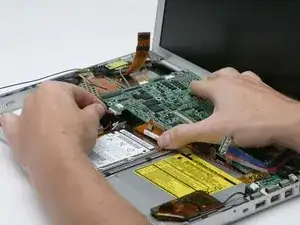
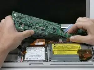
    • Grasp the logic board at the left edge with one hand and at the thinnest section with the other hand. Lift the left edge of the board up to approximately a 30 degree angle (if you don't have your protractor handy, just lift until the DVI port clears the right hinge).

    • Once the logic board clears the ports, slide it out to the left.

  36. AJunELDXq2uBjgRZ
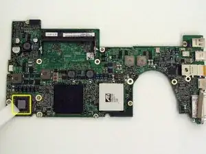
    • Important: when you reinstall a logic board, you'll need to replace the thermal paste that goes between the processor on the logic board and the heat sink. Failure to remove the old paste and apply a new layer can cause the computer to overheat and sustain damage. The following steps refer to replacing the thermal paste between the processor and heat sink; follow these steps only when you are ready to place the logic board in the computer.

    • Use a firm plastic edge to scrape the thermal material off the processor.

    • For more advanced instructions on this procedure, see our Applying Thermal Paste Guide.

  37. RoclbaqUDvaHXdGL
    • Use a firm plastic edge to scrape the thermal material off the heat sink.

    you can also use nail polish remover to get the last of the thermal paste off.

    gsj4gsj -

  38. 4XZIr2XMcirbJFAS
    • Apply a new layer of thermal paste to the copper heat conduit.

    • When replacing the logic board, make sure all cables are routed around and above - not under - it, and to connect the two cables that do go beneath before pushing the board into place.

    • Place the logic board back in the computer, trying not to move it around once the processor has come into contact with the newly-applied thermal paste.

    Don't forget to put thermal paste on the graphic chip.

    justmacs06 -

  39. umOAJh2BoGWGXvJb
    • On computers with an ambient light sensor, you will remove an ambient light sensor board instead of a placeholder yellow plastic board.

    • Remove the two black Phillips screws from the yellow plastic board above the USB port on the left side of the computer.

  40. DSHJuMFJjHaYDTlK
    • Remove the black Phillips screw on the bottom corner of the left speaker board.

  41. dLX1phnXonGkDyCH
    • Remove the nut from the screw just in front of the left speaker.

    Use 4mm nut driver

    nic9 -

  42. OUZW2TY2iTe3wfEB
    • Do not entirely remove the speakers before disconnecting the speaker cable from the sound board.

    • Lift the speaker board up from the computer so that you can access and disconnect the speaker cable from the sound board.

    • Remove the speaker assembly entirely, including the right speaker.

  43. uUTVj11jTAIqWEDX
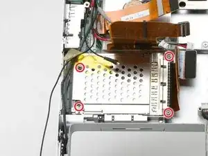
    • Remove the Phillips screw from each corner of the PC card cage (4 screws total).

    • The two longer screws go on the right side of the card cage.

  44. BAmqVN1MrMavKnYl
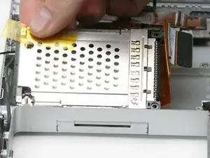
    • Lift the PC card cage up from the front, and remove it from the computer.

    Card cage disassembly: A black plastic piece along the side of the card cage has a tiny hole that mates with a tiny pin sticking up from an aluminum slider. Gently separate the slider pin from the underside of that hole as you lift out the card cage.

    agrich3 -

    Note during reassembly:

    Be SURE to route the Airport antenna cable into the space between the fat Airport ribbon and the card cage, and make sure it's still there when you reinstall the logic board. That antenna cable can slip under the logic board during reassembly, a mistake that you probably won't notice until much later -- when you put the display back on and discover that the antenna connector coming from the display has nothing to plug into.

    agrich3 -

  45. SHYDUYvV2NYC3tts
    • If you have already removed the hard drive or speaker assembly, your computer may differ slightly from the images in this section. These parts do not affect this procedure.

    • Remove the following 7 Phillips screws attaching the heat sink to the metal framework:

    • Five 5 mm screws scattered around the heat sink.

    • One 6 mm on the front left corner of the heat sink.

    • One 10 mm in the back left corner of the left fan.

    You assumed the person who got to this stage had already pulled the display off.

    It has to be noted that you need to take of the display before removing the heatsink or you just won't be able to.

    Carlos Ferrari -

  46. JmpGsgqCEwJgfrFK
    • Remove the heat sink from the case, minding the left corner, as it tends to catch in the case (the fans will come out with the heat sink).

  47. ptVnleZRgPnGNdDU
    • Disconnect the 4-pin power cable and orange ribbon from the DC/Sound card.

  48. BSZVnARjmpdRkZ1V
    • Remove the T8 Torx screw from the RJ-11 board.

    • Remove the 5 mm standoff that secures the DC/Sound card to the lower case using a nut driver or pliers.

  49. wIA5OFGqZHUHUAwB
    • Do not pull the DC/Sound card out entirely. You will be disconnecting the Bluetooth cable in the next step.

    • Lift the DC/Sound card out of the computer and turn it over.

  50. GQRl151nnJCCOyiq
    • Disconnect the Bluetooth cable from the DC/Sound card, removing tape as necessary.

  51. dhLijTMrMj1KCNlm
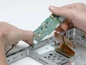
    • Use your thumbs to slide the RJ-11 board away from the sound card in the same direction you would disconnect a cable. This is your chance to get out some aggression, as the board will most likely be very tight and requires a good deal of force to remove. Don't get carried away though - don't hold onto the power connector and don't put too much actual force on the card itself.

  52. b2jUFIlBlQdKxEEl
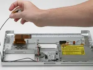
    • Your laptop should look approximately like this.

  53. 2AcxAsROGwnWQrER
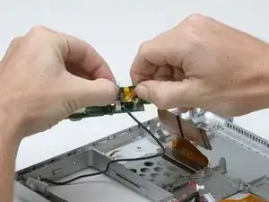
    • Deroute the RJ-11 board cable from along the edge of the case.

  54. KqOUVILHgBPKs3kv
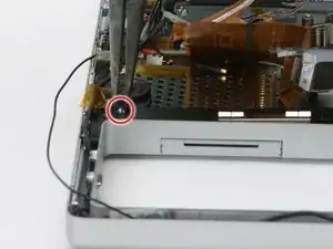
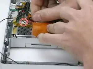
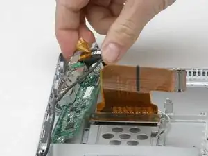
    • Disconnect the RJ-11 cable from the modem.

Abschluss

To reassemble your device, follow these instructions in reverse order.
iRobot

Mitglied seit: 25/09/09

0 Reputation

0 Kommentare