Einleitung

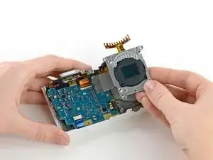
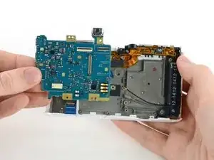
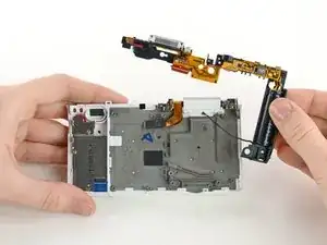
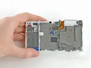
This guide will show you how to remove the flash assembly in the Samsung NX Mini. The flash assembly includes the capacitor, so be sure to discharge the capacitor prior to removal. Learn more about discharging capacitors here.

  1. psgCIinb2HQMroHV
    psgCIinb2HQMroHV
    6yv6OFRTRWGjJuDq
    LZkXwqCYcOK1XgtX
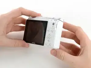
    • Orient the camera so the button panel and LCD are facing you.

    • Use a spudger or fingernail to open the battery compartment on the right side of the camera.

  2. NOJqRWLyWWHfIedp
    NOJqRWLyWWHfIedp
    PGw5WQLbd5UsU1ZT
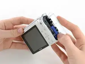
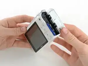
    • Push the blue trapdoor to the left to release the battery, and remove the battery.

    • There is no battery shown in this photo.

    my battery is stuck, is there a manual release button or a way to remove the battery safely?

    beat70 -

  3. usF2HdXjipSkAu65
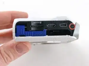
    • Use a Phillips #00 screwdriver to remove the 4 mm screw inside the battery compartment.

  4. FBhJCXxOCVoKTGgA
    • Remove the 4 mm Phillips #00 screw hiding in the external flash port.

    You don't show us how to remove the top plate

    Bev Curran -

  5. RQypSEK2pdXYyDFf
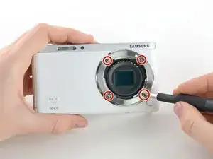
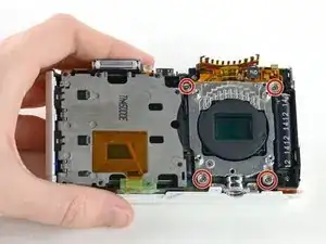
    • Remove the four 5 mm Phillips #00 screws from the lens assembly.

  6. 52UiRHqVkOYpBNq3
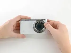
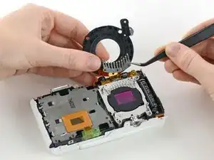
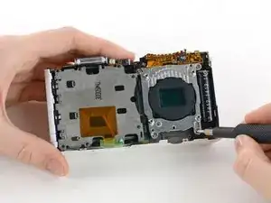
    • Remove the metal lens mount by hand or with tweezers.

    • Be careful not to touch the sensor in the center of the lens assembly.

  7. fuT3A4bYWYT26OFe
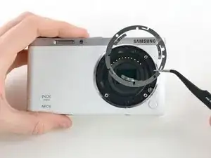
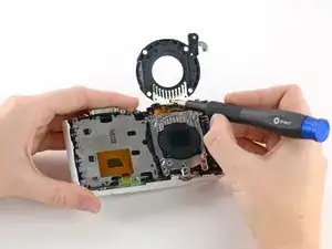
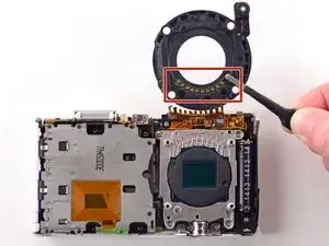
    • Use tweezers to remove the inner metal ring.

  8. n3eyKKDHKE1x6WVH
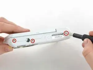
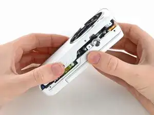
    • Use a Phillips #00 screwdriver to remove the three 4 mm screws from the bottom of the case.

  9. lhXCW5uEdZpJbVWT
    lhXCW5uEdZpJbVWT
    HYEglwV2lN5kAHBD
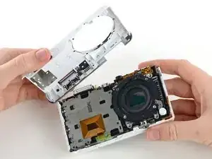
    • Use your hands to slowly pull the front casing away from the camera.

    • The case is attached with multiple clips that may make a cracking noise as you pull it away from the camera.

  10. 5bxPsdobXUhXKRG2
    5bxPsdobXUhXKRG2
    LeBurhyDnv546y4G
    w4jU2XYShyWsFPjy
    • Gently flip the sensor cover back to expose the screw attaching the sensor cover to the ribbon cable.

    • Use a Phillips #00 screwdriver to remove the 3 mm screw from the sensor cover.

    • Use tweezers to remove the metal contact cover. Be sure to carefully remove the cover so the gold contacts remain in place.

    • The gold lens contacts lying beneath the ribbon cable become loose when the screw and contact cover are removed.

  11. OAgp2SpqopONw5nV
    OAgp2SpqopONw5nV
    O6GLTONJMbJMiDjP
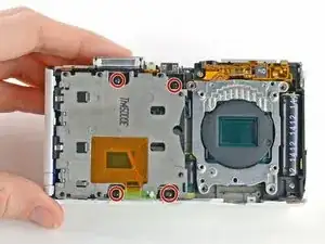
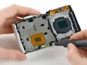
    • Remove the four 4 mm Phillips #00 screws holding the sensor mount in place.

  12. n1EoBerVgoxK5nKQ
    n1EoBerVgoxK5nKQ
    saZACwfTUYYCVJji
    XCqZmVyZQmvHGwpB
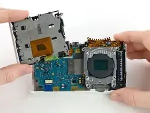
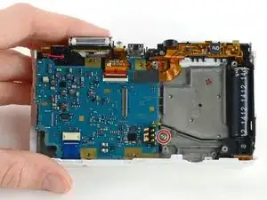
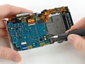
    • Remove the four 4 mm Phillips #00 screws securing the battery compartment to the mother board.

    • Remove the battery compartment.

  13. BWBfAHN2uTvO12Nn
    BWBfAHN2uTvO12Nn
    JlkgIVtduVg4jcJi
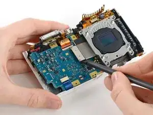
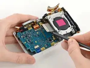
    • Use a spudger to disconnect the ribbon cable connecting the image sensor to the motherboard.

  14. TSGKI1XrLKOSBQoc
    • Gently remove the sensor mount from the camera case.

  15. f3NvCSZMJTo61HY5
    f3NvCSZMJTo61HY5
    HvVh1jtvKNJfDfx6
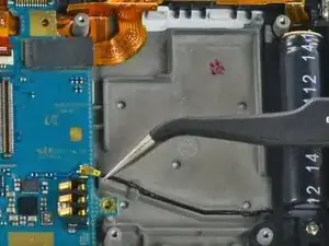
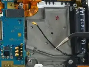
    • Use a Phillips #00 screwdriver to remove the 3 mm screw located below the wifi antenna.

  16. MAOq1wNDFVrT1QuP
    MAOq1wNDFVrT1QuP
    AjPnAEhCZLGIFhni
    • Use tweezers to disconnect the wifi antenna from the motherboard.

  17. kQcBKKrglwduMYPs
    kQcBKKrglwduMYPs
    MFJmTRa4FBiciely
    6u6bDXMYZ5NpN3D3
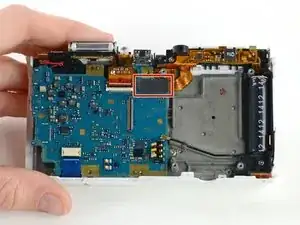
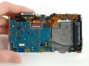
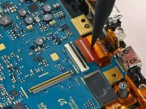
    • Use a spudger to disconnect the LCD ribbon cable by prying it straight up from the motherboard.

  18. rZCJJwwGccIcgbGj
    rZCJJwwGccIcgbGj
    BGAwJj6qUXJR3BaA
    PHkHqOcr4rYsNlHJ
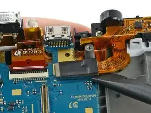
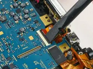
    • Use a spudger to unlock the topmost ZIF connector by flipping open the black flap.

  19. i3p4bTn2iQ3bjXZh
    i3p4bTn2iQ3bjXZh
    3pVnYnkKlFdU2cUy
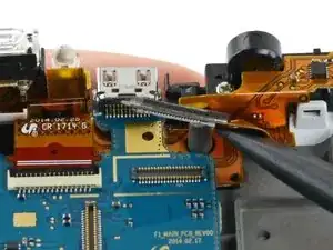
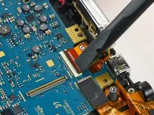
    • Insert the pointed end of a spudger into the hole in the middle of the ribbon cable.

    • Gently pull the spudger back to slide the ribbon cable out of its connector.

  20. fLFvgEBZq4dMUiGr
    fLFvgEBZq4dMUiGr
    a4bTRDcNmyGifnXR
    SriCGaiZvXt1oFdP
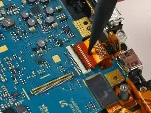
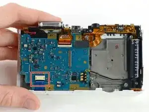
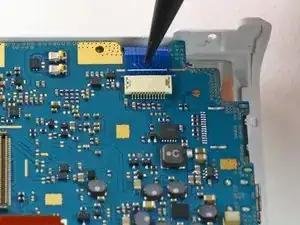
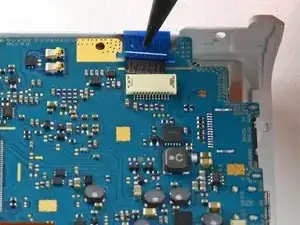
    • Disconnect the blue ribbon cable from the motherboard.

    • Insert the pointed end of a spudger into the hole in the top of the ribbon.

    • Gently pull the ribbon from the connector.

  21. YBbWlZieEx1ELIIC
    • Remove the motherboard from the camera.

  22. Rg1rswSVMUUdslBq
    Rg1rswSVMUUdslBq
    WEtAMOwqUMT6N36T
    QNc6PZkOf6QY3LQT
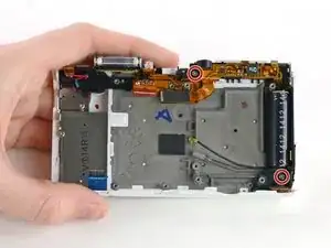
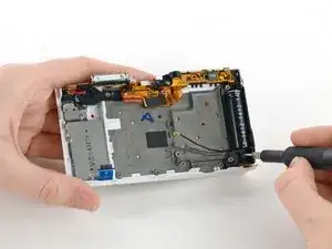
    • Use a Phillips #00 screwdriver to remove the two 5 mm screws holding the flash assembly to the camera case.

  23. kDSKc4UZ6EDbW2VV
    kDSKc4UZ6EDbW2VV
    nCGUwWBNCjIxJDUE
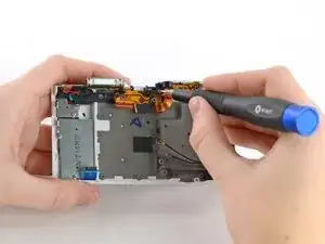
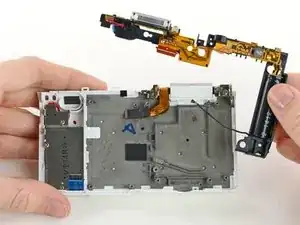
    • Remove the flash assembly by gently pulling it away from the case.

    • You may need to use a spudger to release some of the clips holding the assembly in place.

    • Avoid touching the ends of the capacitor (the large black cylinder on the right). Capacitors that haven't been discharged may cause electric shock. Learn how to discharge a capacitor here.

Abschluss

To reassemble your device, follow these instructions in reverse order.
Kelsea Weber

Mitglied seit: 12/11/15

19058 Reputation

0 Kommentare