Einleitung

Folge dieser Anleitung, um das Display deines Steam Decks zu ersetzen. Das Vorgehen für Displays mit geätztem, entspiegeltem Glas ist identisch zu normalen Displays.

Beachte während der Reparatur die allgemeinen Vorsichtsmaßnahmen zur Vermeidung von elektrostatischen Entladungen (ESD = engl. electrostatic discharge).

Anmerkung: Solltest du ein Display für 512 GB Modelle in ein 64/256 GB Gerät, oder umgekehrt installieren, muss ebenfalls ein passendes Display-Flexkabel installiert werden. Beide Arten von Displays haben unterschiedliche Flexkabel.
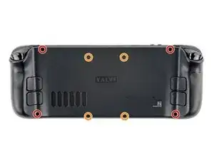
  1. vQyR3PAE4HOMSLAZ
    vQyR3PAE4HOMSLAZ
    aIKAs5r3P3bY2iTE
    hD1USYJCkAbkluud
    • Schalte das Steam Deck ein und entlade den Akku auf unter 25%, bevor du mit der Reparatur beginnst. Aus einem geladenen Lithium-Ionen-Polymer-Akku können gefährliche Chemikalien austreten, wenn er versehentlich angestochen wird.

    • Valve empfiehlt als zusätzliche Sicherheitsmaßnahme den Akku im BIOS in den battery storage mode (Akkuspeichermodus) zu versetzen, bevor du mit Reparaturen an inneren Bauteilen anfängst. Hier steht, wie das geht.

    • Schalte das Steam Deck komplett aus und ziehe alle Stecker ab.

    • Wenn du eine microSD-Karte angeschlossen hast, dann musst du sie entfernen, bevor du das Steam Deck öffnest. Wenn du die Rückseite ausbaust, ohne die Karte zu entfernen, kann sie in zwei Teile zerbrechen.

    • Es kann hilfreich sein, wenn du während der Reparatur das Steam Deck mit der Oberseite nach unten in seine Hülle legst, um die Joysticks zu schützen und Wackeln zu vermeiden.

  2. bpUGGPG32OkLXnC4

    there should be a picture of the SD card slot at the start of every Steam Deck teardown. i know the note is there but i generally use the pictures to guide me and forgetting to remove the SD card is a very critical step

    Nathan Barrow -

    I agree, I just broke mine...

    Camille B -

    What is the the #1 philips used for? Only the #0 is mentioned in the instructions.

    Christopher Martin -

    I wish they would specify which size to use for which screws.

    Mark D -

    I found it easiest to use a PH1 for the red screws, and PH0 for the rest (including the internals.)

    Chris Clawson -

    Be careful you can strip the screws take your time

    I use PH00 bit

    jaybush74 -

    I used the PH1 bit for this. You can use smaller bits but ideally there should be no play of the bit in the screw head.

    Charles Semple -

    are there playstation replacements (circle,square,cross,triangle)

    Deór -

    I used the ifixit tools and used the 00 size for the screws on the back.

    Luis B -

    I've completed the guide and found it very helpful!

    I think somewhere in this part it would be helpful to name the size of the correct Phillips driver to use:

    Use a Phillips driver to remove the eight screws securing the back cover:

    Four 9.5 mm screws

    Four 5.8 mm screws

    Maynard -

    I used the PH1 for the 9.5mm screws and PH00 for the 5.8mm screws. The PH0 wanted to strip one of the small ones.

    Pol Llovet -

  3. 6jtVcFtMGa5ZMqcF
    6jtVcFtMGa5ZMqcF
    Ux5LEj3JfJlkmQMQ
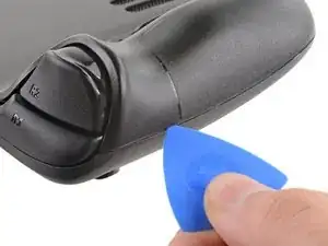
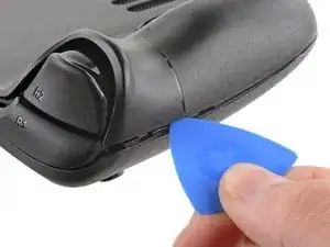
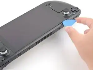
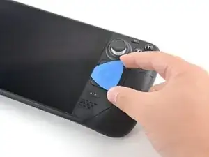
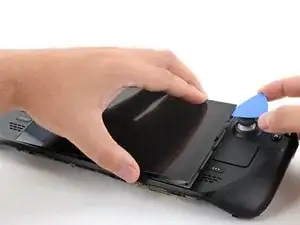
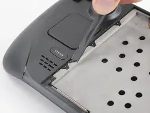
    • Setze ein Plektrum in die schmale Fuge zwischen Rückabdeckung und Vorderschale an der Kante des rechten Griffs ein.

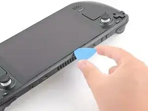
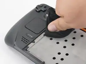
    • Heble die Rückabdeckung hoch, um sie aus den Clips zu lösen, mit denen sie befestigt ist.

    I found it easiest to start this process at the top of the device near the fan exit.

    Peter Lindberg -

    second that and inserting the pick in the bottom middle and sliding the pick to each side

    Sub -

    I also found the top near the fan exit to be easier

    Travis Patton -

    Thank you for this tip, it definitely was easy starting at the top instead of by the bumper/triggers. After I opened the top I did the bottom and then it was way easier to gently open the sides. be very careful and go slowly to make sure that none of the clips are damaged

    Luis B -

    this as suggested above:

    1. open the top

    2. open the bottom

    3.gently open the sides

    austrasier -

    same; i pried from the top of the screen area. I was unable to find an opening on the side

    Dennis Wu -

    I also started from the middle of the deck and worked my way out since I couldn't get a grip with the pick on the deck's side grips. Since this is a common step for pretty much all guides for opening the deck I think it's also worth noting that you should be careful not to bend the trims/seams where the front and back covers meet with the pick. When I first opened my deck you can definitely see where I nudged the pick in between the covers since I was probably using too much force on the pick itself.

    Kaleb McKone -

    It would be useful to note here that if you want to insert the little blue triangular iFixit opening picks into the right side along the edge, there isn't actually a gap as the directions say, at least not on newer Decks. You'll be making the initial gap using the pick. Brace it on something because you will need to use enough downward force that you're flexing the pick a bit and it'll probably be digging into the skin of a bare hand. With enough force suddenly it will make a click and go in just a bit, and then you're in business.

    CaptFrost -

    plastic picks didnt work for me but finger males did the job on prying this open

    jacobbagsic -

    I found it easiest to open starting with R1 or L1 buttons and proceeding to the center of the top edge

    Karol Gro -

  4. 6IvIWWqEXPTqW1XB
    6IvIWWqEXPTqW1XB
    1FxwYDjIGOAOCZT2
    KpIx4YIAZrDH1b5T
    • Wenn alle Clips von einer Kante gelöst sind, kann der Rest ganz einfach entfernt werden.

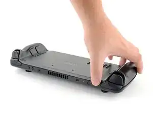
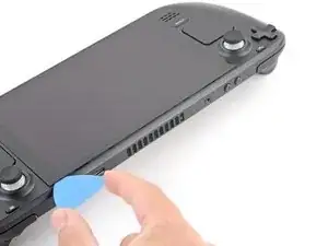
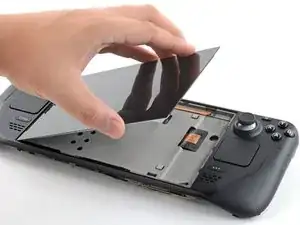
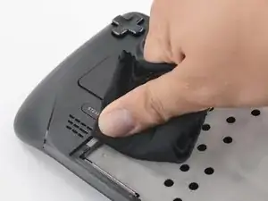
    • Fasse die Rückabdeckung an der Öffnung, die du gerade erstellt hast, und ziehe sie nach oben vom Gerät weg, um die Clips an den langen Kanten zu lösen.

    • Entferne die Rückabdeckung.

    If you have an SD card, you will want to take it out. I followed the guide and didn't think about the SD card I had inside. When I went to snap the case back on it clapped shut on the exposed SD card, shearing it in half and leaving the bottom half stuck in the SD card slot. I am still endeavoring to get it out.

    Novice -

  5. WuMbLgtJF5JwQtjF
    WuMbLgtJF5JwQtjF
    I6pEKNGEKEDbNymT
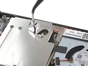
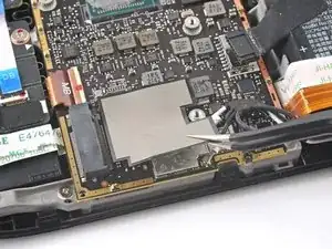
    • Entferne mithilfe einer Pinzette das Stück Klebefolie auf der versteckten Schraube auf der Platinenabschirmung.

    • Versuche die Klebefolie nach Möglichkeit nicht zu zerreißen, sodass sie wiederverwendet werden kann. Wenn es nötig ist, kannst du dir auch ein passendes Ersatzstück aus Aluminiumfolie zurechtschneiden und einkleben.

    Use some heat here from a hairdryer to make this part easier.

    If you screw up here you can replace the little aluminium square with some aluminium tape from Amazon. No less than 50 microns thick, slightly thicker is fine. and the square is 13mm both ways.

    Matt S -

  6. fpjCmGxopRvFvGbm
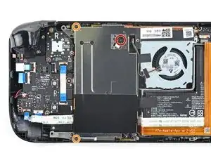
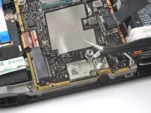
    • Benutze einen Schraubendreher, um die drei Kreuzschlitzschrauben zu entfernen, mit denen die Abschirmung der Platine befestigt ist:

    • Eine 3,4 mm Schraube

    • Zwei 3,7 mm Schrauben

    The procedure ended here for me, used an ifixit PH 00 bit on the screw behind the aluminium tape, bit wouldnt bite too great, one wrong twist and the screw was stripped. Not sure who or what initially screwed in that particular screw as the rest of the screws on the shield were fine, but boy is it in there tight. So now i have a stripped screw and a botched ssd replacement, don't think valve will let me RMA for this, but i'll give it a try and update accordingly.

    Y. van S -

    Any updates? Did they let you RMA?

    Emanuel Gjoni -

    I found one screw to be ridiculously tight too, managed to undo it without stripping thanks to reading your comment beforehand and going extra careful. Not going to lie, it was a tense moment :D

    Andy HL -

    I think the tendency is to go too small on the screwdriver bits because you're working on small electronics.

    I used the PH1 bit on the screw under the foil and the PH0 bit for the two remaining screws without any problems.

    Charles Semple -

    What does this shield actually do? Some kind of magnetic protection?

    Corey Cleric -

    if I had to replace the key (R2) and that's it, can I directly remove it or do I have to act here on the motherboard too?

    pujattidanny -

    have you gotten an answer yet? trying to change mines as well but dont wanna do too much to the deck

    briaNN -

    button Not key, i’m sorry

    pujattidanny -

    I used the ifixit tools and used the 00 PH for these screws with no issue

    Luis B -

    If only swapping the SSD, it is not necessary to remove the top left 3.7mm screw. The heat shield is flexible enough that you can move it out of the way to access the SSD screw. For me this was necessary as the 3.7mm screw was completely unmovable and quickly stripped.

    Scott A -

    FYI there is a little pin on the cover that slots into the board. It is located near the top screw. I needed that to be inserted for the cover to go back down properly.

    Seth Robinson -

  7. JXePTdtVUbrOvVJT
    JXePTdtVUbrOvVJT
    QqjInaZugM3yJK1q

    When putting back on, run a pick along the edge of the shield between the wires to make sure nothing is pinching and the wires are clear of the shield before screwing down.

    Matt S -

  8. XjI1homB4a5VNhbV
    XjI1homB4a5VNhbV
    qvcjxPUTxawsUUMB
    qa3R33nVHlO1SOpy
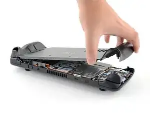
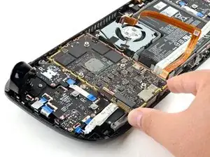
    • Fasse das Akkukabel an seiner Zuglasche und ziehe es vom Motherboard weg, um es abzutrennen.

    • Du kannst den Stecker auch mit dem flachen Ende des Spudgers aus seinem Anschluss herausschieben und dann endgültig mit der Hand abtrennen.

    After fully reassembling my device I found that my battery was not showing any stats anymore. I couldn't start the device without being plugged in, however if I restarted it would stay on even if my power cable was detached. Battery showed 0%. It turns out I had not fully reinserted the battery cable at this stage during reassembly. MAKE SURE YOU PUSH IT ALL THE WAY BACK IN!

    Michael Hoffmann -

    Awesome thanks for this tip!

    petergeranio -

    It is helpful to lift up gently with a the tapered end of a spudger underneath the tucked-in portion of the battery cable, creating a bit of flex in the cable before pulling on the pull tab. I found that without doing so, the fabric pull-tab simply tore off of the cable under light-to-moderate force (the fabric itself ripped cleanly across, like a paper towel). Careful, gentle pressure with a spudger can be used to remove the plug by prying gently on the rear ridge of the plastic plug (not the wire!) if this happens.

    Gene Eckser -

    This is exactly what happened to me. Maybe it was a pull tab previously, mine was a ribbon cable that tore - captured the image here: https://www.ianwootten.co.uk/2022/11/22/...

    Ian Wootten -

    I found it less scary and easier to remove the battery connection by using a fingernail on the ridge and pushing it off the connector. I felt like pulling on the battery cable was too harsh.

    montgomery mchargue -

    Upon plugging the battery back in, I found it easy to use two spudgers- one on each side- to pull/push the connector back into it's port. Be careful to not put any pressure on the battery wires themselves.

    montgomery mchargue -

    When reconnecting the battery cable, you'll know when it's inserted and power is restored, because the white LED will illuminate at the top of the Deck near the power button. You should be able to see it while you're reconnecting the battery cable

    Michael Davis -

    Why not just let the battery discharge completely and then not have to disconnect it?

    Jeffrey Martin -

    Completely discharging a battery reduces its lifespan. It's completely unnecessary.

    Stefan Camporese (CENTER) -

    Because no lipo battery is ever completely discharged -- you would not be able to recharge it if it was. There will always be enough power left in it to cause damage if shorted even if it isn't charged enough to power up the device it's connected to.

    David Cameron -

    I would personally not recommend pulling the tab. It doesn’t apply force at the correct angle. You should revise these instructions to advise using a combination of pulling on the tab, and careful pressure on the connector towards the right of the mainboard to carefully work it out.

    Using the pull tab alone could cause problems if not done extremely carefully.

    William Winborne -

    This part was wayyyyy easier than I anticipated and I worried for nothing because I used the ifixit spudger to push it out a bit and then I literally used my finger nail and was able to slide it right off. Dont be afraid, its not that difficult and its not that delicate to break if you do it patiently

    Luis B -

    I inserted the cable very firmly with a spunger, being careful not to press down too hard on the cables, and even tried redoing it, but I don't see any LED illumination. I am now unable to boot the deck into the boot manager. Any additional tips?

    junefish -

  9. Wb1NxBPPT1PSBhGc
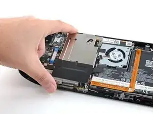
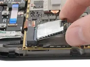
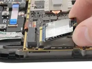
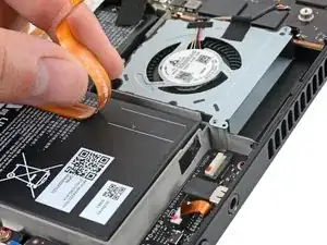
    • Benutze einen Kreuzschlitzschraubendreher, um die 3,4 mm Schraube zu entfernen, mit der die SSD befestigt ist.

  10. kqxseNHvcfLUVJ6f
    kqxseNHvcfLUVJ6f
    meWZB2YOQ3H6FFlF
    • Sobald die SSD-Schraube entfernt ist, löst sich die SSD in einem flachen Winkel ab.

    • Fasse die SSD und ziehe sie von ihrem M.2 Platinenstecker weg, um sie zu entfernen.

    • Setze die SSD beim Zusammenbau wieder in einem flachen Winkel in ihren Platinenstecker ein, und befestige sie mithilfe der SSD-Schraube in ihrer horizontalen Position.

  11. 4KYHMASkPWuBgLsb
    4KYHMASkPWuBgLsb
    v3awsxt21JOONI25
    nFSu2fKNDSTMEhRG
    • Benutze eine Pinzette, um den Sticker an der Oberkante des Lüfter abzulösen.

    • Versuche den Sticker nach Möglichkeit nicht zu zerreißen, sodass er wiederverwendet werden kann. Wenn nötig, erwärme ihn etwas, um den Kleber aufzuweichen.

    • Wenn du den Eindruck hast, dass der Sticker doch anfängt zu reißen, dann ziehe ihn an einer Ecke mit einer Pinzette soweit hoch, dass du ihn mit den Fingern fassen kannst. Entferne ihn dann per Hand.

    It's not super clear from the pictures but you're aiming to remove the black strip, not just the small white square sticker. Use heat and go slowly.

    Matt S -

    I didnt like using the tweezers for this part because the sticker was so stuck that it felt like using the tweezers was going to rip it. I used the tweezers to lift it a bit and used my finger to gently lift the rest.

    Luis B -

    You don't need to remove the sticker entirely from the heat sink, just the side where it sticks to the fan. At least on mine, the black sticker was 80% on the heat sink, so it was much easier to just peel off the thin strip from the fan

    jamesmiglietta -

  12. gY3xLKZClleZl5E1
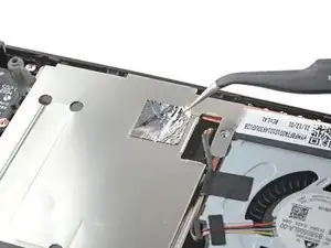
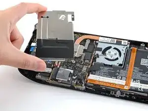
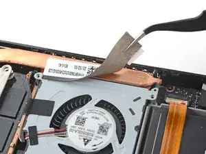
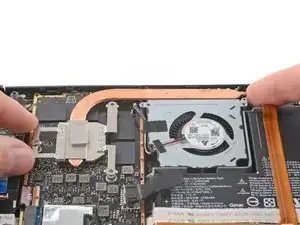
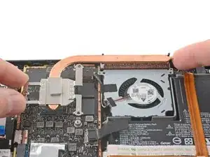
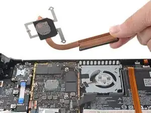
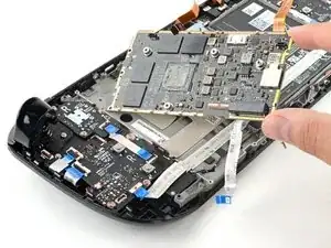
    • Benutze einen Schraubendreher, um die beiden Kreuzschlitzschrauben zu lösen und zu entfernen, mit denen der Kühlkörper am Motherboard befestigt ist:

    • Eine unverlierbare 3,5 mm Schraube

    • Eine 3,4 mm Schraube

    • Nein, der Schein trügt nicht! Die dritte Schraube am Kühlkörper wurde an einem früheren Zeitpunkt der Demontage entfernt, sie dient nämlich auch als versteckte Schraube an der Platinenabschirmung.

  13. IJVMpPZxyKXYxycU
    IJVMpPZxyKXYxycU
    wPADiEDDdwgoHY1B
    gHCDRt1kBBeBV5lx
    • Hebe den Kühlkörper an und entferne ihn.

    • Bevor du den Kühlkörper wieder einbaust, folge dieser Anleitung, um den Kühlkörper und die APU zu reinigen und neue Wärmeleitpaste aufzutragen.

    Where i can buy this heatsink?

    Savatium -

  14. OvORxayh4RiWnAZN
    OvORxayh4RiWnAZN
    EhNZsRDjhxmxFZSt
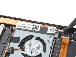
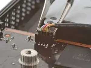
    • Fasse die Kanten des Lüftersteckers mit einer Pinzette und ziehe den Stecker hoch, um ihn vom Motherboard abzutrennen.

    • Ziehe das Lüfterkabel an seinem Stecker heraus und nicht an den Kabeln.

  15. DnwyiGY2AVoOYPKi
    DnwyiGY2AVoOYPKi
    TaJSIHBqFfQeEkYA
    nq2SHFSPjDBduMUO
    • Löse das WLAN Abschirmband mit einer Pinzette ab und entferne es.

    • Versuche, es nach Möglichkeit nicht zu zerreißen, damit es wiederverwendet werden kann. Wenn nötig, kannst du es leicht erwärmen, um den Kleber aufzuweichen.

    The steam deck looks to be shipping now with an additional plastic sheet adhered to the wifi module meant to better retain the connectors in place, that will have to be removed.

    Stephen Micheals -

  16. TTxtBvaYgmXmfATn
    TTxtBvaYgmXmfATn
    XfVrKYPd32E3bI5x
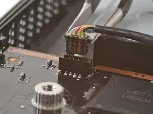
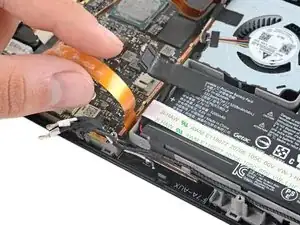
    • Fasse die Kanten des Lautsprechersteckers mit einer Pinzette und ziehe den Stecker nach oben, um ihn vom Motherboard abzutrennen.

    • Ziehe das Lautsprecherkabel an seinem Stecker und nicht an den Kabeln heraus.

  17. h364fIg4JEiN2A5e
    h364fIg4JEiN2A5e
    2NLPHTCGwlkCsTgk
    tMUWXkFbQbAJ3Pho
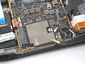
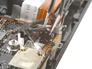
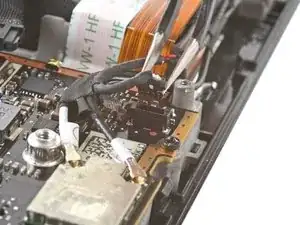
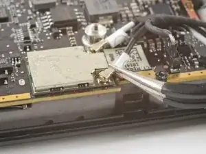
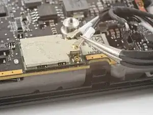
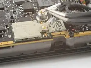
    • Fasse den Antennenstecker mit einer Pinzette so nah wie möglich an seiner Basis.

    • Ziehe ihn gerade nach oben, um das Kabel abzutrennen.

    • Wiederhole das beim zweiten Antennenkabel.

    • Achte beim Zusammenbau darauf, dass beide Antennenkabel wieder in ihren entsprechenden Anschlüssen verbunden werden. Die Markierungen as den Kabeln entsprechen denen auf dem WLAN-Modul.

    • Richte die Stecker direkt über ihren Anschlüssen aus und drücke sie nach unten, bis sie einrasten, um die Kabel wieder zu verbinden.

  18. wipsSoHZIAFacUnU
    wipsSoHZIAFacUnU
    3QrRocRn5pQpncgo
    fcBR1JXIrcaZbo3P
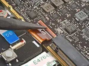
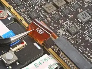
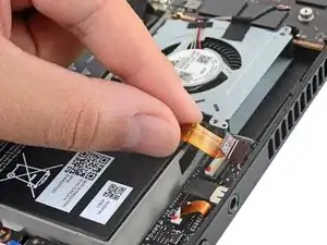
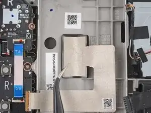
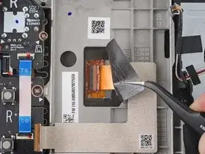
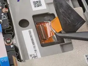
    • Hebe den kleinen Sicherungsbügel am ZIF-Verbinder des Displaykabels mit der Spudgerspitze hoch.

    • Schiebe das Kabel mit einer Pinzette aus seinem Anschluss.

    • Fasse das Kabel an seiner Zuglasche, nicht am Kabel selbst.

  19. 6DQuNR5Y6rsaLQjZ
    6DQuNR5Y6rsaLQjZ
    HH6aIJQsNHPiGCLn
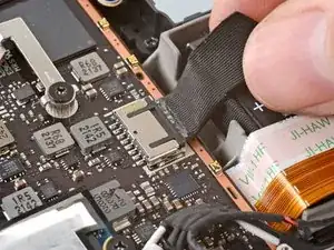
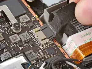
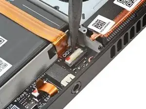
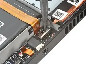
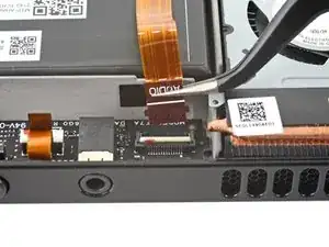
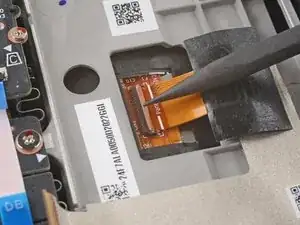
    • Hebe den kleinen Sicherungsbügel am ZIF-Verbinder des Audio-Kabels mit der Spudgerspitze hoch.

    FYI the locking flap was not white, but black on my model.

    David VanWormer -

  20. R1yZ43JZRvyinp3e
    R1yZ43JZRvyinp3e
    ToKZe3vl1l5LcKkZ
    • Schiebe das Kabel mit einer Pinzette aus seinem Anschluss.

    • Fasse das Kabel an seiner Zuglasche, nicht am Kabel selbst.

  21. KhaG3LgcGMPBx23A
    KhaG3LgcGMPBx23A
    KoLE1DNtjjNbH11o
    itQjy6SQXGCsmFcH
    • Löse das Audio-Kabel vorsichtig vom Akku ab.

    • Das Audio-Kable ist leicht auf dem Akku festgeklebt.

    • Falls der Kleber zu hartnäckig ist, erzwinge es nicht. Erwärme das Audio-Kabel leicht mit einem iOpener oder einem Fön, um den Kleber aufzuweichen.

  22. kYSvKNUtoMKW1Y52
    kYSvKNUtoMKW1Y52
    MQPeMMWRLhmlbXK1
    nBqwGC62TGpBgPpA
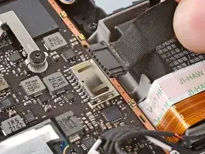
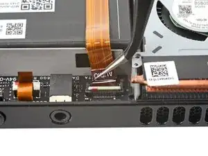
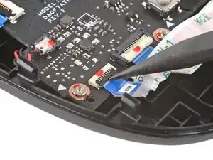
    • Hebe den kleinen Sicherungsbügel am ZIF-Verbinder der Tastenplatine mit der Spudgerspitze hoch.

    • Ziehe das Kabel mit einer Pinzette aus seinem Anschluss.

    • Fasse das Kabel an seiner Zuglasche und nicht am Kabel selbst.

    Please note, when replacing the button board cable, and when removing the motherboard, there may be adhesive that sticks the DB cable to the ribbon cable underneath it, which is the Interconnect Cable, to the right of the image above.

    Since the adhesive will stick that cable to the Interconnect Cable, the DB cable that connects to the BOTTOM of the motherboard may disconnect from its zif connection. You will have to connect the DB cable that connects to the underside of the Steam Deck's motherboard first to ensure the connection from the DB to the button board is established. This can be tested in the BiOS as basic directional pad and A and B buttons should be functional in the BiOS or Recovery Menu.

    Opz Sigma -

  23. UHBoaExoNLL1SisX
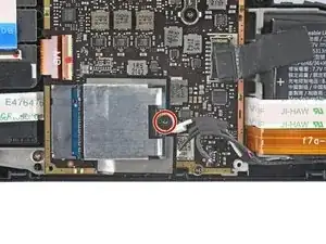
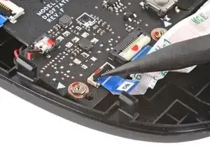
    • Benutze einen Schraubendreher, um die drei 3,7 mm Kreuzschlitzschrauben zu entfernen, mit denen das Motherboard befestigt ist.

  24. RMPjNALMnObtFSYG
    RMPjNALMnObtFSYG
    wpyiINS4QdZm41rq
    twpyRfSXp5JJPaft
    • Entferne das Motherboard.

    • Das Audio-Kabel sowie das Kabel der Tastenplatine sind über ZIF-Stecker mit der Unterseite des Motherboards verbunden.

    On replacement, check all the way around the motherboard for trapped cables!

    Mark H -

    Second the above, the DB cable is usually attached to the underside of the motherboard, however due to adhesive that the DB cable is ontop of, when removing the motherboard it can disconnect the DB cable from the motherboard.

    Also this is important to make sure that the following aren't inaccessible when re-installing the motherboard:

    Heatsink Fan near top-right
    MB cable to display near bottom left
    Speaker and Wi-Fi cables near bottom right
    DB cable that connects underneath Motherboard near bottom left
    HD Audio cable underneath Motherboard near bottom right

    Opz Sigma -

    Peux ton changer le lecteur sd ??

    Il est défectueux

    d.karimali -

  25. cYnFCMsvPOo5WOEg
    cYnFCMsvPOo5WOEg
    sUfHjsAJf21owXxL
    • Löse mithilfe einer Pinzette den Sticker ab, der den Displaystecker bedeckt.

    • Versuche den Sticker nach Möglichkeit nicht zu zerreißen, sodass er wiederverwendet werden kann. Wenn nötig, kannst du ihn etwas erwärmen, um den Kleber aufzuweichen.

  26. YonEpIZKct6GAGCe
    YonEpIZKct6GAGCe
    o1ktxYTdqJOqfQpF
    QRILfND2JaF6XooU
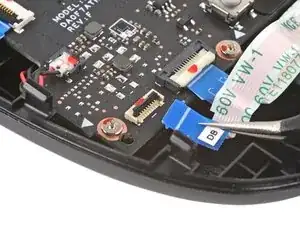
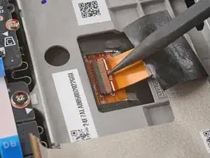
    • Benutze die Spudgerspitze, um den kleinen Sicherungsbügel am ZIF-Stecker des Displaykabels hochzuheben.

    • Schiebe das Kabel mit einer Pinzette aus seinem Anschluss heraus.

    If the screen is glowing after turning it back on after re assembly but it’s showing blank, did I not reconnect the display correctly or is it something else?

    Noah Buller -

  27. rXaMWSCVrQomEZJT
    • Bereite einen iOpener vor und lege ihn eine Minute lang auf die Oberkante des Displays.

    • Du kannst auch eine Heißluftpistole oder einen Fön benutzen, aber achte darauf das Steam Deck nicht zu überhitzen, die Displays und die internen Akkus sind beide hitzeempfindlich.

  28. 6QvN3mrFwqLKCYjY
    6QvN3mrFwqLKCYjY
    FJkHVYcMD3CBHFdi
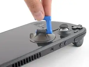
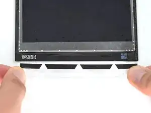
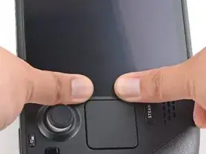
    • Setze einen Saugheber an der oberen linken Ecke so nahe wie möglich an der Kante auf das Display und drücke ihn fest.

    • Wenn dein Display stark gebrochen ist, kann es hilfreich sein, es mit durchsichtigem Klebeband abzukleben, damit der Saugheber besser hält. Alternativ, kann auch starkes Klebeband statt des Saughebers benutzt werden. Wenn das alles nichts bringt, klebe den Saugheber mit Sekundenkleber fest.

  29. B3lJZSmYJPafMgs6
    B3lJZSmYJPafMgs6
    KLIJDLqPkMmUFBh1
    Cg3cxCQBdCguUXkB
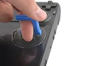
    • Ziehe mit starker, gleichmäßiger Kraft am Saugheber, um einen Spalt zwischen Display und Gehäuse zu schaffen.

    • Setze die Spitze des Plektrums in den Spalt.

    • Setze das Plektrum nicht weiter als ~3 mm (1/8 Zoll) unter das Display, um zu vermeiden, dass das Displaypanel, der Umgebungslichtsensor oder das empfindliche Kabel darunter beschädigt werden.

    The suction cup simply does not lift up the screen enough to insert the pick - there is no gap. No matter how much heat.

    Ebben -

  30. BLjseWEKCXJN2y6R
    BLjseWEKCXJN2y6R
    y5ESCln2LrNpHMwD
    GseATLllxX4c1Qy1
    • Schiebe das Plektrum an der Oberkante des Displays entlang, um den Kleber aufzutrennen.

  31. 31knYnAjEQoWbwkk
    • Erhitze die rechte Kante des Displays eine Minute lang.

  32. jhRqLsbxO4jHXPqQ
    jhRqLsbxO4jHXPqQ
    BPNMbWkVZxFVFLXE
    BXYG2DjhI2RcK3d1
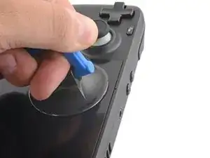
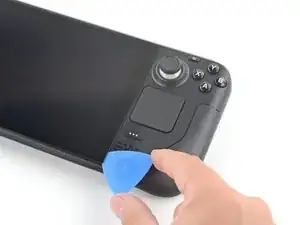
    • Schiebe das Plektrum an der rechten Kante des Displays nach unten, um den Kleber aufzutrennen.

  33. lc2JJaQbUuxRi3d3
    • Erhitze die untere Kante des Displays eine Minute lang.

  34. MrQUNrkGNLQH3SBO
    MrQUNrkGNLQH3SBO
    wHNYW6PFxJouQ6Rq
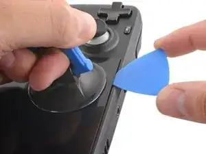
    • Schiebe das Plektrum an der unteren Kante des Displays entlang, um den Kleber aufzutrennen.

  35. jPpbRalwMhRRokWX
    • Erhitze die linke Kante des Displays eine Minute lang.

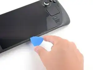
    • Schiebe das Plektrum an der linken Kante des Displays entlang, um den Kleber aufzutrennen.

  36. PgrPrAkaDKe12Gy2
    PgrPrAkaDKe12Gy2
    3PNaNiUYnMYEViIC
    2ynLpaCpW1qGto36
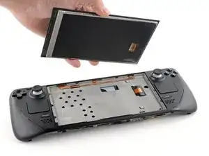
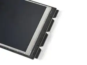
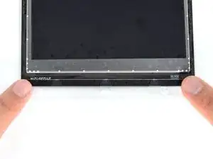
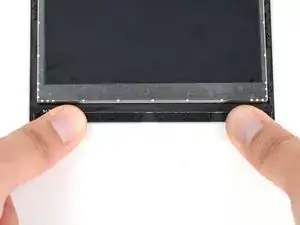
    • Sobald du den Kleber rund um das Display aufgetrennt hast, hebe vorsichtig die rechte Kante des Displays an, als würdest du ein Buch öffnen.

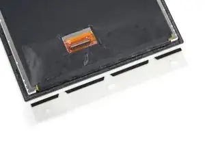
    • Entferne das Display.

  37. lEuDDqNOQcdmaoYW
    lEuDDqNOQcdmaoYW
    RilvDrKSSYM5ZFiy
    kJlXiTElISKc6HdR
    • Während des Wiederzusammenbaus:

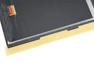
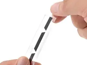
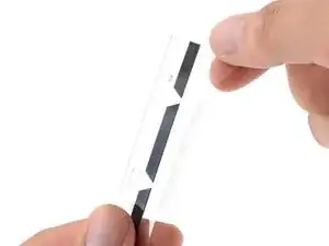
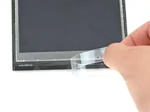
    • Sieh dir die neuen Display-Klebestreifen an und ordne jeden Streifen der korrekten Seite des Displays zu.

  38. jjk6LmO3ySpCHanP
    jjk6LmO3ySpCHanP
    H6P3sbIQHckQvWXD
    • Um sicherzustellen, dass die neuen Klebestreifen korrekt haften, müssen alle Klebeflächen gründlich gereinigt werden.

    • Große Klebstoffrückstände können mit dem flachen Ende eines Spudgers oder einem Öffnungswerkzeug aus Kunststoff entfernt werden.

    • Benutze keine Werkzeuge aus Metall, da diese die Oberfläche verkratzen können.

  39. OdsiRiulQpAscUW2
    OdsiRiulQpAscUW2
    UC5wUnG1xBRVI1fA
    • Benutze Klebstoffentferner oder Isopropylalkohol (>90%), um Klebstoff- Rückstände zu entfernen. Wische solange mit einem fusselfreien Tuch oder Kaffeefilter über die Klebfläche, bis alle Kleberückstände weg sind. Wische immer nur in eine Richtung.

    • Isopropylalkohol kann zwar ohne Bedenken zum Reinigen elektronischer Geräte verwendet werden, er löst aber bestimmte Schaumstoffklebstoffe. Achte beim Reinigen darauf, nicht zu viel Alkohol zu verwenden und diesen nur auf die zu reinigenden Stellen zu beschränken.

    • Bevor du das Gerät zusammenbaust, lasse allen verbleibenden Isopropylalkohol verdunsten.

  40. bUKLRBVmXV6fQumC
    bUKLRBVmXV6fQumC
    CYIDChWBgHJRJTtd
    • Bevor du die Folie einer der Klebestreifen abziehst, prüfe erneut, wohin der jeweilige Streifen geklebt werden muss.

    • Sobald du dir sicher bist, wo der Klebestreifen hin soll, zieh die Folie ab, so dass die Klebefläche des Streifens frei liegt.

    • Sei vorsichtig mit freiliegenden Klebestreifen. In den meisten Fällen ist es nicht möglich, Klebestreifen nochmal abzuziehen und erneut anzubringen, wenn du sie beim ersten Mal falsch angebracht hast.

  41. yX5xOxvaAsFQOBuo
    yX5xOxvaAsFQOBuo
    SjlIDkvQXD5MU2yA
    oSC6gY4XDoKDUQTy
    • Halte den freiliegenden Klebestreifen an den Laschen und richte ihn so aus, dass die Kante des Streifens mit der Außenkante des Displays übereinstimmt.

    • Benutze dein altes Display als Referenz um nachzuprüfen, wo die Klebestreifen an den Kanten des neuen Displays angebracht werden sollen.

    • Sei vorsichtig mit dem Ausrichten der Klebestreifen. In den meisten Fällen ist es nicht möglich, Klebestreifen nochmal abzuziehen und erneut anzubringen, wenn du sie beim ersten Mal falsch angebracht hast.

    • Setze den Klebestreifen auf die Oberfläche auf und drücke ihn gut mit den Fingern fest.

    • Wiederhole die vorherigen zwei Schritte für die restlichen drei Display-Klebestreifen.

  42. HH2TyS6xnna5Bexi
    • Ziehe die verbleibende Plastikfolie von allen vier Klebestreifen ab, um die Klebefläche freizulegen.

    • Wiederhole diesen Schritt für alle vier Klebestreifen. Achte darauf keine der freiliegenden Klebeflächen zu berühren.

  43. 5mZR6DpoPGIMDsbs
    5mZR6DpoPGIMDsbs
    h1ZYblF35lKRKIdr
    • Setze das neue Display auf den Mittelrahmen auf und drücke es 20-30 Sekunden lang an den Kanten fest, um eine gute Klebeverbindung sicherzustellen.

Abschluss

Um dein Gerät wieder zusammenzubauen, folge den Schritten dieser Anleitung in umgekehrter Reihenfolge.

Entsorge deinen Elektromüll fachgerecht.

Lief die Reparatur nicht wie geplant? Versuche es mit einigen grundsätzlichen Lösungsansätzen, ansonsten findest du in unserem Steam Deck Forum Hilfe bei der Fehlersuche.

Carsten Frauenheim

Mitglied seit: 10/03/20

88317 Reputation

8 Kommentare

Attempted this tonight after smashing the screen on my deck. Easy to follow and worked flawlessly first time. Thank you

Matt Willis -

On peut mettre un autre ecran OLED ou autre ?

lapartdesanges50 -

This guide is gold standard. Not once did I think “why didn’t they mention this?”

Lenny Zappa -

Woop Woop Fixed my screen after my anker powerbank fell on it

trevor.davis.1990 -

Thanks for the guide! I just replaced my Steam deck screen. Guide was simple and straight forward

Manni Live -

I did the tutorial to the exact way explained and it’s working perfectly. Thank you kind souls.

Dallas Hall -

Clear and concise. Worked first time with little to no experience working on electronics. Thank you very much!

James Butler -

Super easy to follow, thanks so much! The comments on each step were also super helpful. <3

Jeff Larsh -